
This post is an addition to my previous post: “How to flash bios chips with Arduino“.
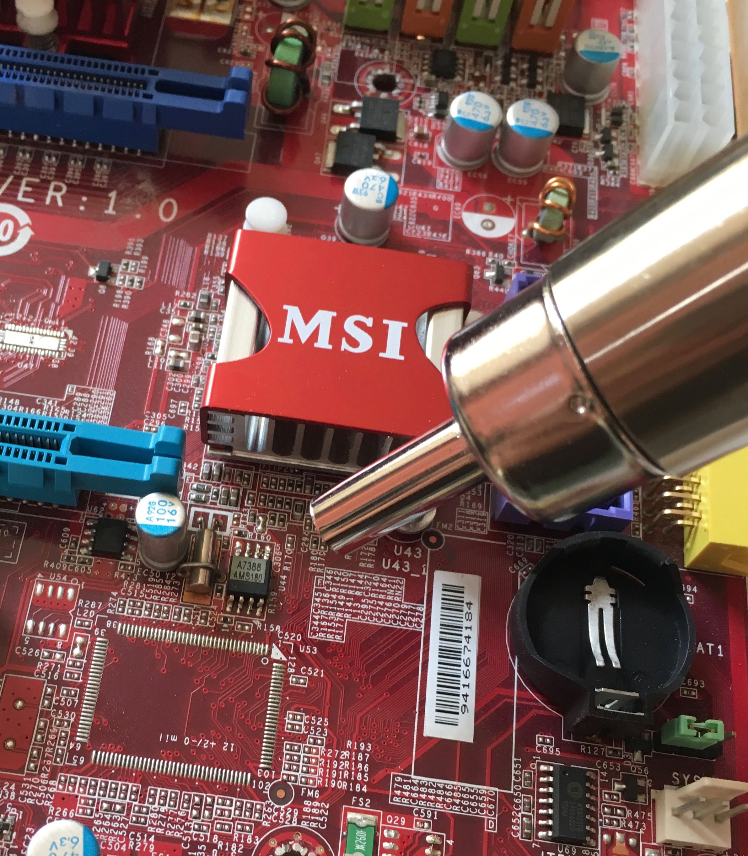
While doing some research online I found several articles/posts from people using a Raspberry Pi to flash SPI flash chips. Apparently the Raspberry Pi is very suitable for this kind of thing as it has a SPI interface and is able to run linux. I was eager to try this out for myself so I got out my Pi 3 model B and got to work. For this project I used a Winbond 25X80 salvaged from a motherboard I had lying around.
Outline of steps:
- Preparing the Raspberry Pi
- Enabling the SPI interface
- Installing flashrom (either from source or via apt get)
- Connecting the Raspberry Pi to the chip
- Using flashrom to interact with the chip
Preparing the Raspberry Pi
As others have pointed out, the latest version of Raspbian (Stretch) will also work by adding the spispeed param to the Flashrom command.
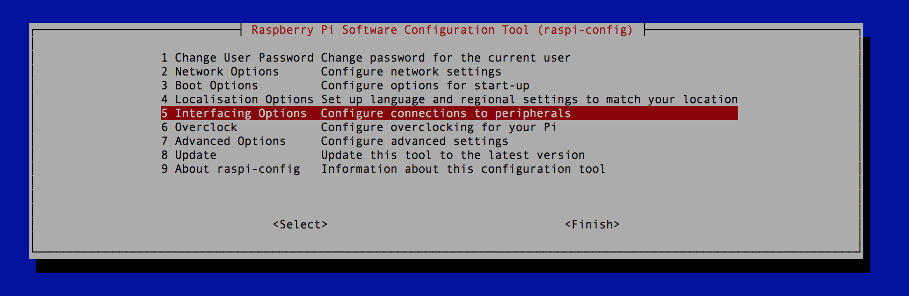
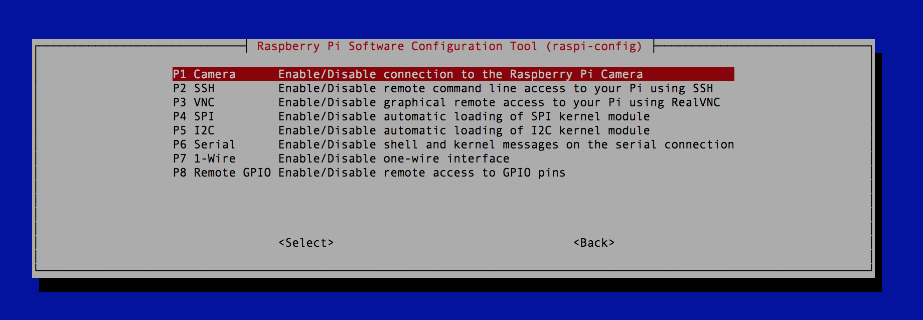
Enabling the SPI interface
The SPI interface are enabled by typing sudo raspi-config and selecting P4 SPI under the Interfacing options. After which the SPI interface will become available under:
- /dev/spidev0.0
- /dev/spidev0.1
Installing flashrom
Installing flashrom can be done via a simple apt-get or from source. To install from source first install the dependencies:
sudo apt install git libpci-dev libusb-1.0 libusb-devFinish up by cloning the flashrom repo, compiling and installing flashrom:
git clone https://github.com/flashrom/flashrom.git
cd flashrom
make
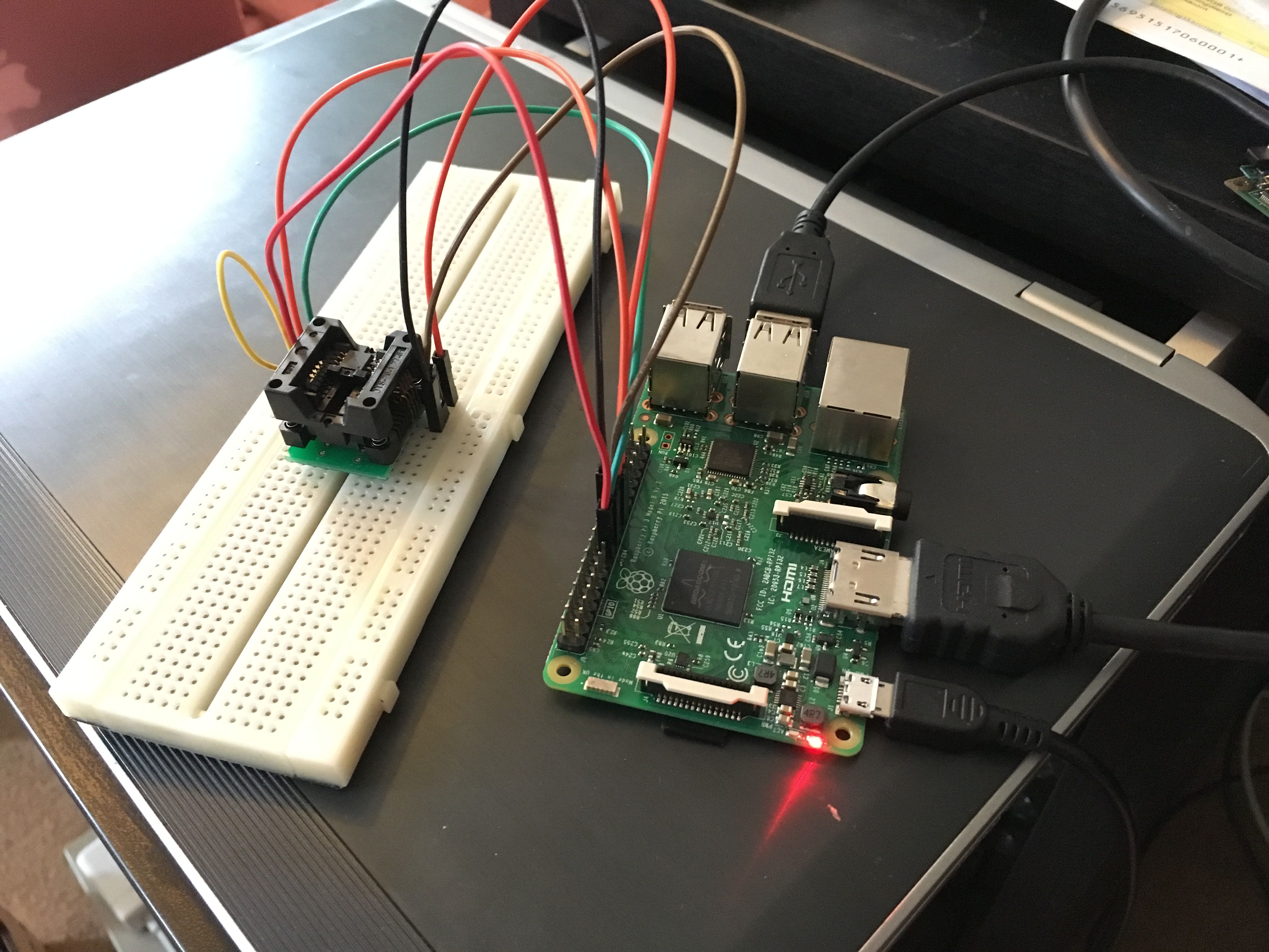
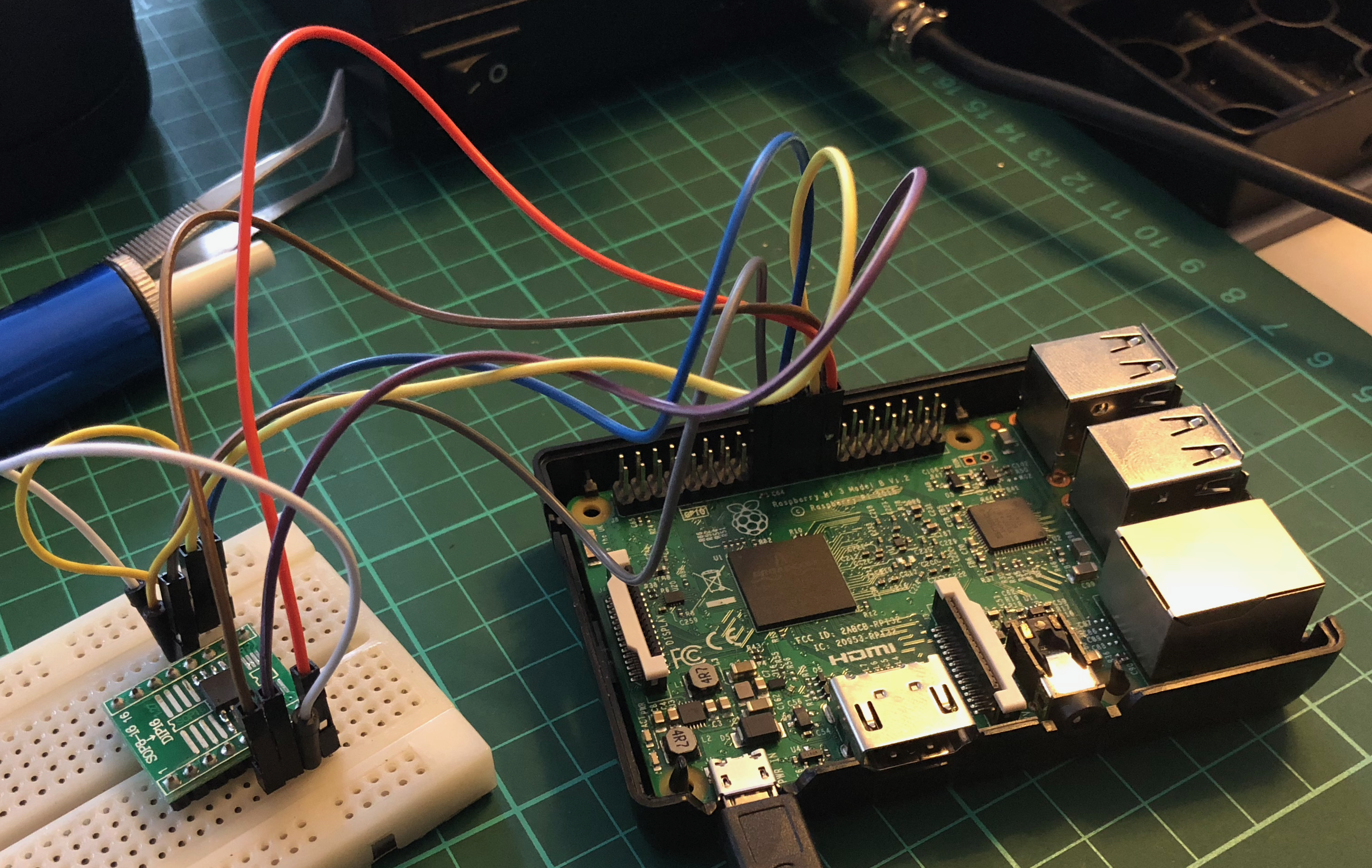
sudo make installConnecting the Raspberry to the SPI flash chip
The table below show the connections between the RaspberryPi and the chip.
| RPi pin | SPI flash |
|---|---|
| 25 | GND |
| 24 | CS |
| 23 | SCK |
| 21 | DO |
| 19 | DI |
| 17 | VCC 3.3V and /HOLD and /WP |
Interacting with the chip
In order to verify flashrom correctly identifies the chip we run flashrom without any operations.
$ flashrom -p linux_spi:dev=/dev/spidev0.0,spispeed=512


flashrom p1.0-76-g291764a on Linux 4.14.34-v7+ (armv7l)
flashrom is free software, get the source code at https://flashrom.org

Using clock_gettime for delay loops (clk_id: 1, resolution: 1ns).
Found Winbond flash chip "W25X80" (1024 kB, SPI) on linux_spi.
No operations were specified.
Now that Flashrom correctly identifies the Winbond W25X80 we can continue to backup the current BIOS.
$ flashrom -p linux_spi:dev=/dev/spidev0.0,spispeed=512 -r [
oldbios]

flashrom p1.0-76-g291764a on Linux 4.14.34-v7+ (armv7l)
flashrom is free software, get the source code at https://flashrom.org

Using clock_gettime for delay loops (clk_id: 1, resolution: 1ns).
Found Winbond flash chip "W25X80" (1024 kB, SPI) on linux_spi.
Reading flash... done.
After backing up the old BIOS we can safely write the new BIOS back to the chip.
$ flashrom -p linux_spi:dev=/dev/spidev0.0,spispeed=512 -w [newbios]


flashrom p1.0-76-g291764a on Linux 4.14.34-v7+ (armv7l)
flashrom is free software, get the source code at https://flashrom.org

Using clock_gettime for delay loops (clk_id: 1, resolution: 1ns).
Found Winbond flash chip "W25X80" (1024 kB, SPI) on linux_spi.
Reading old flash chip contents... done.
Erasing and writing flash chip...
Warning: Chip content is identical to the requested image.
Erase/write done.
References:
- https://github.com/flashrom/flashrom
- https://www.flashrom.org/RaspberryPi
- http://dalincom.ru/datasheet/W25X80.pdf
Thank you for this post. I was able to fix my Asrock x79 Extreme4-m with this technique.
You’re welcome!
Hello. I am getting this error when installing flashrom on raspberry pi 3,
internal.c:148:32: error: ‘par_master_internal’ defined but not used [-Werror=unused-const-variable=]
static const struct par_master par_master_internal = {
^~~~~~~~~~~~~~~~~~~
cc1: all warnings being treated as errors
Makefile:1043: recipe for target ‘internal.o’ failed
make: *** [internal.o] Error 1
occurs after (sudo make)
Your help is much appreciated
Hi,
Thanks for the comment.
I will try and reproduce this error on my pi.
Will be back later with a response.
Kind regards,
Tom
Hi,
I’ve redone the steps but I did not come across this error.
What raspbian distro are you using?
I’m using Jessie lite.
Kr,
Tom
Hi,
I am using jessie lite too. same error on latest version 2 previous versions.
But I managed to install it with apt-get install flashrom, and its working now,
Thank you very much
Amr
Hi,
Good to hear you got it working.
What board or computer did you revive?
Tom
Trying to revive a bricked GPU CARD..( MSI RX580 GAMING X) The bios chip is ( winbong w25x40cling)
still no luck reading it with permona soic 8 test clip..
will keep you updated
Many thanks
Nice, good luck.
Watch the wiring and changing the spispeed to 512 might improve your chances.
edit the Makefile before you run make
and change the CFLAGS line
CFLAGS ?= -Os -Wshadow -Wno-unused-parameter
Cheers for the CFLAGS fix! Compiled fine on latest Raspbian 9.3 Stretch.
And thanks for the guide Tom!
You are welcome! I’m glad people are helping each other out in the comments.
It seems there are some issues when using the Flashrom version from github.
Would be interesting to see if these problems are solved when installing Flashrom using apt-get.
I will test this and update the post when I have the result.
Hi Kjetil,
I’ve tried both versions of Flashrom (from github and the standard debian repo) but neither seemed to work for me when using Raspbian Stretch. Flashrom was not able to recognize the SPI flash chip. Next I reverted to Raspbian Jessie lite and compiled Flashrom from github. Now Flashrom did identify the SPI flash chip and I could read en write to it. Did Flashrom work for you on Stretch?
Kind regards,
Tom
Hey Tom,
So that explains my issues with recognizing the flash, didn’t have much time when I compiled it, and after a few attempts I put it aside.
I can confirm that reverting to Stretch and compiling from git it not detects the flash on first try.. Shows me right for trying to squeeze in some fun before leaving for work.
Thanks again for the follow up, you saved me hours of cursing and debugging I’m sure!
Hi Kjetil,
Thank you for confirming my suspicion about Stretch. I’ve updated my post and included a link to the specific Raspbian Jessie image I used. Let me know if this image works for you.
Probably entirely too late to help your situation, but in case future readers find themselves in the same predicament, here is the solution:
“sudo make WARNERROR=no”
and that is all you should need to do to resolve it! 🙂
Pingback: Flashing a bios chip with an Arduino
Pingback: coreboot for CompuLab Intense PC | «WatchMySys» Blog
s/not/now/
Hi Tom, first off, thanks for the awesome tut, it’s brought me closer to rescuing my motherboard than anything else so far.
I am having a similar issue to Kjetil though in that Flashrom (both apt-get version and the freshly compiled repo source) fail to identify the chip:
“pi@raspberrypi:~/bios $ sudo flashrom -p linux_spi:dev=/dev/spidev0.0 -w E7760IMS.C80
flashrom v0.9.9-91-g0bfa819-dirty on Linux 4.9.59-v7+ (armv7l)
flashrom is free software, get the source code at https://flashrom.org
Using clock_gettime for delay loops (clk_id: 1, resolution: 1ns).
Found Generic flash chip “unknown SPI chip (RDID)” (0 kB, SPI) on linux_spi.
===
This flash part has status NOT WORKING for operations: PROBE READ ERASE WRITE
The test status of this chip may have been updated in the latest development
version of flashrom. If you are running the latest development version,
please email a report to [email protected] if any of the above operations
work correctly for you with this flash chip. Please include the flashrom log
file for all operations you tested (see the man page for details), and mention
which mainboard or programmer you tested in the subject line.
Thanks for your help!
Error: Image size (8388608 B) doesn’t match the flash chip’s size (0 B)!”
I’ve double checked that the chip is supported (it’s the MSI motherboard MS-7760), I’ve double and triple checked the wiring to the JSPI1 header (9-pin variant) and I’ve tried pulling the hold pin high, low and even leaving it disconnected…
So far, no dice though.
Have you encountered this kind of issue before or do you have any ideas as to how I might be able to either solve or refine the problem further?
Hi Minothor!
Did you use the jessie image I linked to in the post?
Flashrom is refusing the see the SPI chip when using Raspbian Strech.
Using Raspbian Jessie fixed the issue.
Kind regards,
Tom
You Hit the Nail on the Head!
Turns out I was using Stretch, Jessie Lite detected it fine!
Great!
Enjoy your fixed Motherboard! 🙂
Am doing so! Thank you so much! Seeing it load the Bios after 3 weeks was just pure joy!
I’m going to reflash the B chip now so I have an on-board backup!
Hello,
Thanks for your work.
I’ll try to revive an old laptop bricked ages ago.
I was wondering if I can solder small wire on the chip to avoid to desoldering the winbond 25q128fv..
Regards
You’re welcome! Maybe you could try using a special clip voor in circuit programming? They can be bought for cheap from China I think.
Thanks for the hint !!
Aliexpress or ebay is fine.. 1.5€ is OK, and it might save lots of work.
Neverthless I’ll have to tear down the laptop as there’s very little space near the chip.
I’ll keep you informed.
Please do! I always like hearing back from people.
Just ordered the clip+ribbon+breakboard adapter plate…
Now patience begin…
Another thing… I extract the exe from the bios upgrade file.. and theris x2 .bin file.. 8mB each.. wondering which is the good one…
Have a look on ebay for “SOIC 8 clip” you’ll save yourself a lot of effort.
Thanks for your help.
Regards.
I love your tutorial! I just have a quick question before proceeding ( it’s my first rodeo):
For pin #17 it says the following “VCC 3.3V and /HOLD and /WP” – does that mean that I either:
1. Connect ONLY the VCC BIOS pin to RPI pin #17, while leaving the other BIOS pins (HOLD, WP) disconnected altogether?
2. Or, do I simply connect all 3 BIOS pins (VCC, HOLD, WP) to the same RPI pin #17??
Thank you very much!!
Hi! It’s option two. So connect pin 17 to Vcc Hold and Wp. Easy option is to connect pin 17 to vcc and add jumper wires from there to wp and hold.
Okay sounds good!! I was thinking option #2 would be correct but didn’t want to chance it and fry the chip or PI itself, as would be my luck.
Thanks again.
Waiting for the SOIC8 clip to arrive I prepare my jessie sdcard.
I downloaded the jessie version you mention to avoid compatibility problems.
I follow your instructions but I have a problem with “make && make install”.
make report a problem : fatal ambiguous argument ‘hooks/’ : unkown revision or path not in the working tree
Of course the commands ends with :
make: *** [install] error 1…
I removed flasrom directory and redownloaded (re-git clone it) it.. same problem..
Any idea please.
This probably (not 100% sure) has to do with a bad clone from GIT. Could you show the commands you are using?
After installing Jessie (full version),
“pi@raspberrypi:~/flashrom $ cat /etc/os-release
PRETTY_NAME=”Raspbian GNU/Linux 8 (jessie)”
”
I copy/paste your suggested command
pi@raspberrypi:~ $ git clone https://github.com/flashrom/flashrom.git
Cloning into ‘flashrom’…
remote: Counting objects: 9886, done.
remote: Compressing objects: 100% (87/87), done.
remote: Total 9886 (delta 86), reused 111 (delta 69), pack-reused 9730
Receiving objects: 100% (9886/9886), 3.04 MiB | 42.00 KiB/s, done.
Resolving deltas: 100% (7517/7517), done.
Checking connectivity… done.
Seems OK…
Then make && make install…
and aleas :
“fatal: ambiguous argument ‘hooks/’: unknown revision or path not in the working tree.
Use ‘–‘ to separate paths from revisions, like this:
‘git […] — […]’
Checking for a C compiler… found.
Target arch is arm
Target OS is Linux
Checking for FTDI support… not found.
Checking if Linux SPI headers are present… yes.
Checking for utsname support… found.
Checking for clock_gettime support… found.
mkdir -p /usr/local/sbin
mkdir -p /usr/local/share/man/man8
mkdir: cannot create directory ‘/usr/local/share/man/man8’: Permission denied
Makefile:1382: recipe for target ‘install’ failed
make: *** [install] Error 1”
Thanks for your help….
follow it.
Hello worked late on it..
I tried stretch with gui and succeded to install flashrom.
I installed the utilities and set to on the spi in raspberry parameters.
To do so I downloaded the 1.0 version from flashrom unziped it cd flashrom make make install and no error message.
I launched a flashrom -r and no message… as I have no attached soic8 it seems logical… Just wondering why it doesn’t detect that tjere’s nothing connected….
Did you keep the ” -p linux_spi:dev=/dev/spidev0.0″ between flash roman and the -r?
That tells flashrom what hardware to use for reading/writing.
(in this case, the pi’s pins)
Hi, as mentioned before Strech will not work. Even if you are able to compile and install flashrom, flashrom will not recognize your chip. It’s best to stick to the Jesie version I linked to. If flashrom fails to compile try installing it trough apt-get. I believe both versions should work.
I worked on it again… using
sudo make
Replacing all version templates with 0.9.9-117-g305a2b3.
fatal: ambiguous argument ‘hooks/’: unknown revision or path not in the working tree.
Use ‘–‘ to separate paths from revisions, like this:
‘git […] — […]’
Checking for a C compiler… found.
Target arch is arm
Target OS is Linux
Checking for libpci headers… found.
Checking version of pci_get_dev… new version (including PCI domain parameter).
Checking if libpci is present and sufficient… yes.
Checking for libusb-0.1/libusb-compat headers… found.
Checking if libusb-0.1 is usable… yes.
Checking for libusb-1.0 headers… found.
Checking if libusb-1.0 is usable… yes.
Checking for FTDI support… not found.
Checking if Linux SPI headers are present… yes.
Checking for utsname support… found.
Checking for clock_gettime support… found.
then
sudo make install
Replacing all version templates with 0.9.9-117-g305a2b3.
fatal: ambiguous argument ‘hooks/’: unknown revision or path not in the working tree.
Use ‘–‘ to separate paths from revisions, like this:
‘git […] — […]’
Checking for a C compiler… found.
Target arch is arm
Target OS is Linux
Checking for FTDI support… not found.
Checking if Linux SPI headers are present… yes.
Checking for utsname support… found.
Checking for clock_gettime support… found.
mkdir -p /usr/local/sbin
mkdir -p /usr/local/share/man/man8
install -m 0755 flashrom /usr/local/sbin
install -m 0644 flashrom.8 /usr/local/share/man/man8
Eventhough “fatal: ambiguous argument ‘hooks/’: unknown revision or path not in the working tree.” it seems OK :
flashrom
flashrom 0.9.9-117-g305a2b3 on Linux 4.9.35-v7+ (armv7l)
flashrom is free software, get the source code at https://flashrom.org
Please select a programmer with the –programmer parameter.
Previously this was not necessary because there was a default set.
Valid choices are:
dummy, gfxnvidia, drkaiser, satasii, atavia, it8212, serprog, buspirate_spi,
dediprog, pony_spi, nicintel, nicintel_spi, nicintel_eeprom, ogp_spi, linux_spi,
pickit2_spi, ch341a_spi.
Then :
flashrom -p linux_spi:dev=/dev/spidev0.1
flashrom 0.9.9-117-g305a2b3 on Linux 4.9.35-v7+ (armv7l)
flashrom is free software, get the source code at https://flashrom.org
Using clock_gettime for delay loops (clk_id: 1, resolution: 1ns).
No EEPROM/flash device found.
Note: flashrom can never write if the flash chip isn’t found automatically.
flashrom -p linux_spi:dev=/dev/spidev0.1 -r YOURBIOS
flashrom 0.9.9-117-g305a2b3 on Linux 4.9.35-v7+ (armv7l)
flashrom is free software, get the source code at https://flashrom.org
Using clock_gettime for delay loops (clk_id: 1, resolution: 1ns).
No EEPROM/flash device found.
Note: flashrom can never write if the flash chip isn’t found automatically.
As I ain’t got the SOIC8 clip… it’s normal…. I guess
I was able to reproduce the error you got: “fatal: ambiguous argument ‘hooks/’: unknown revision or path not in the working tree.”. I’m guessing this is due to a recent update in the flashrom github. You could fall back to an older version or install via apt-get. But as you stated earlier although the error occurs, flashrom will still finish. And yes sudo is required to make install, sorry for that.
Tried it with an older revision, same error. Don’t know enough about github to pinpoint the problem but if it works it works. 🙂
I urge to recieve the soic clip to test.
I’ll keep you informed.
Thanks for your help.
For user using Stretch, reducing speed (spispeed) should work :
sudo flashrom -p linux_spi:dev=/dev/spidev0.0,spispeed=512
Hello,
I succeeded in wiring the bios directly on the motherboard, thanks to your tutorial !!!
My problem was that SOIC8 clip cablewiring is somewhat illogical to me. Happily for me my multimeter solved the problem.
I first red the bios to save it in a file just in case.
Then I erased the chip to avoid any problem, and to check if chip is OK…
Then I tried to restore the bios I downloaded BUT ,(did you noticed that problem always occurs with “But”), the file is only 8MB… and the chip is 16MB…
–> flashrom forbid me to write the 8MB file….
What is strange is that the bios file (a self exe) containt x2 8MB files :
L77_0142.bin
L78_0142.bin
Both .bin contain data…
But when I create a bootable USB Bios update key, it only contains : L78_0142.bin which is 8MB
Any idea is very welcome…
I found a 16MB version of the bios file… it worked !!
Thanks again for sharing this tutorial !!
Fantastic! Glad you got it to work and that my write-up was of use to you. 🙂
Hi
I have bricked MSI B250M Mortar MB with winbond “25q128fvsq”
Is it possible to flash it with raspberry PI Zero WH ? (Pi Zero is a little bit cheaper)
As pi zero w handle spi too there is no reason for it not to work.
Double check gpio pin bit it should work as per rpi 2 3..
in case anyone has problem with unknown flash error
add parametter “,spispeed=512” or “,spispeed=30000”
like so:
detect flash
flashrom -p linux_spi:dev=/dev/spidev0.1,spispeed=512
make backup
flashrom -p linux_spi:dev=/dev/spidev0.1,spispeed=512 slowbackup.rom
write flash
flashrom -p linux_spi:dev=/dev/spidev0.1,spispeed=512 -w newbios.rom
read and check
flashrom -p linux_spi:dev=/dev/spidev0.1,spispeed=30000 -r newbackup.rom
diff slowbackup.rom newbackup.rom
Thank you for this guide it has really helped me with the proposed flashing of libreboot to to the SPI (Winbond W25X64) chip of my Lenovo T400 laptop.
In the guide it says (RPi pin 23)to be connected to the (SPI flash pin SCK).My data sheet for the (Winbond W25X64) doesn’t list a SCK pin but it does list a CLK (serial clock input) pin.
Would that be the same?
Correct, sck is the same as clk. Good to hear my post was of help to you! 🙂
Hi
I got the latest full raspbian from raspberry pi main site.Installed flashrom from the add remove programs bit then enabled spi from config window, rebooted then opened a terminal and
I used
sudo su
then I used
flashrom -p linux_spi:dev=/dev/spidev0.1,spispeed=512
but that did not find the chip so without changing the setup I used
flashrom -p linux_spi:dev=/dev/spidev0.0,spispeed=512
and it promptly found it .
The only difference was spidev0.1 was changed to spidev0.0
This might help anyone who uses the newest raspbian gui version on the pi
Hi Casper,
I took some time to update my post to reflect this information.
Thank you!
Thanks again got the libreboot.rom flashed to the board last night
Hi, I tried with the latest raspbian (debian 9.4 stretch) but flashrom does not find the chip (winbond w25x32). I also tried to compile flashrom from github and changed the device (both /dev/spidev0.0 and 0.1) but without luck. Any ideas ?
maybe I have to downgrade to jessie ?
Hi,
Can you show me the command(s) you use and the output?
Flashrom should work fine with stretch as long as you use the spispeed parameter.
Hi, I have sent a reply some days ago but maybe it’s not arrived.
Anyway, I have installed jessie and built flashrom from source. But I haven’t solved the problem. Now I come back to stretch and the following is the output of flashrom (pkg):
# flashrom -p linux_spi:dev=/dev/spidev0.1,spispeed=500
flashrom v0.9.9-r1954 on Linux 4.14.70-v7+ (armv7l)
flashrom is free software, get the source code at https://flashrom.org
Calibrating delay loop… OK.
No EEPROM/flash device found.
Note: flashrom can never write if the flash chip isn’t found automatically.
I have also tried the following command with the same output:
# flashrom -p linux_spi:dev=/dev/spidev0.1,spispeed=500
# flashrom -p linux_spi:dev=/dev/spidev0.1,spispeed=1000
# flashrom -p linux_spi:dev=/dev/spidev0.1,spispeed=2000
# flashrom -p linux_spi:dev=/dev/spidev0.1,spispeed=3000
and:
# flashrom -p linux_spi:dev=/dev/spidev0.0,spispeed=500
# flashrom -p linux_spi:dev=/dev/spidev0.0,spispeed=1000
# flashrom -p linux_spi:dev=/dev/spidev0.0,spispeed=2000
# flashrom -p linux_spi:dev=/dev/spidev0.0,spispeed=3000
and:
# lsmod|grep -i spi
spidev 16384 0
spi_bcm2835 16384 0
I have also changed the raspberry itself, I mean I have inserted the fresh installed raspbian sd on an other raspberry, but nothing was changed.
Also I have an anomaly.. when I reboot I have a kernel crash, I don’t have the log but the problem seems to concern the bcm2835 driver. About this I am a bit confused because I don’t know if it is the wifi driver or the spi driver. In the log there was printed exactly bcm2835 but an lsmod|grep bcm give me only spi_bcm2835 and btbcm..
Anyway now I try to built flashrom from source.
Hi,
it seems flashrom is working fine but your chip is not detected. Have you checked the wiring?
Yeah, the wires are ok, I have changed it with others. But I have a doubt, the wire on rp 17 pin is connected to three wires that on my chip are connected to the 3,7 and 8 pins (/WP /HOLD and VCC). Is it correct ?
This is the shot from the winbond w25x32 datasheet pdf: http://imgur.com/doCogqhl.png
Hi,
That should be correct. Could you upload a picture showing how you wired the Raspberry Pi to the chip?
Hi Tom, sure I take the picture, but before two things:
1) a guy on #flashrom@freenode says to check the wires length that shouldn’t be more than 10 cm. Then I have cut the wire(s) connected to the pin 17 because it was 20 cm (the first wire)+20 cm (the other three wires). Then from the pin 17 to the chip it was about 40 cm of wire.
2) After cut the wire from 40cm to 22 cm I have powered on the raspberry again but it seems doesn’t want to power on.. the pin 17 wires are a bit warm.. then an other guy on freenode has said me to desolder the chip… ?!?!?!
Hi Frank,
I think you should take a step back and rethink your approach before continuing. I can confirm that wire length is an issue as longer wires pick up noise which will interfere with programming. I would not recommend desoldering chips just yet. Let’s start with a picture of how you connected everything and maybe some more info on the machine you are trying to fix?
Kind regards, Tom
Hi Tom,
well the following are the pics of the wires. The white wire is the pin 1.
https://imgur.com/a/miklRAv
https://imgur.com/a/ajvNaRf
Thanks for the pictures. However, would it be possible to make a picture showing how the raspberry pi and the winbond chip are connected (preferably in one picture)? I can’t make out from the current pictures if the wires go to the correct pins on the chip. Do you have the datasheet for the Winbond chip?
The datasheet should be this:
http://support.spectrumdigital.com/boards/dskda830/revf/files/102801-0001R-SPIFlash.pdf
I don’t understand very well your first question. I mean, to see how they are connected u have to follow the colored wire. For example:
The pin17 on rpi (yellow wire) is connected to 3 wire (two orange and one red). Those 3 wires are connected to the pins 3, 7, 8 on the winbond chip.
The pin19 on rpi (blue wire) is connected to the pin 5 on the winbond chip.
and so on..
Then:
rpi pin17(yellow)–>Clip pin3 (orange,/WP),pin7(orange,/HOLD),pin8(red,VCC)
rpi pin19(blue)–>Clip pin5 (DI0)
rpi pin21(grey)–>Clip pin2 (D0)
rpi pin23(purple)–>Clip pin6 (CLK)
rpi pin25(black)–>Clip pin4 (GROUND)
rpi pin24(white)–>Clip pin1 (/CS)
Then I connect the clip pin 1 aligned with the pin 1 on the flash chip.
I don’t know if my previous message was arrived. Anyway the pc is an old desktop “HP Compaq 8000 Elite Small Form Factor”. Chipset “Intel Q45 Express”. If u want I can take a pic of the winbond chip.
Thank you.
PS Can I ask you your email? I want ask you something in private.
Hi, in my case I have a 25Q32 and want to copy its code to a 25Q128 (old answering machine) to quadruple its available memory. Has anyone ever done this?
Extra bonus points: has anyone ever recovered a chip which seems to have flipped bits. I suspect its just old age but if I can identify which ones don’t correspond to the stock image it may be repairable.
-Andre
Thank you for this fantastic post, which I cite here: http://posts.nadim.computer/2018/10/26/repairing-a-thinkpad.html
Hi Nadim! Congrats on the awesome blogpost. I’m glad my post was useful to you.
Pingback: 2 – Repairing a ThinkPad with a Corrupt Thunderbolt Firmware Chip | Traffic.Ventures Social
Hi, I´m trying to unbrick a TP-Link WR740N, download the firmware from their website but say not match
Error: Image size (4063744 B) doesn’t match the flash chip’s size (4194304 B)!
Anyone knows about solve this issue?
Thanks!!
HI Sergio,
I found the following which seems to fit your issue: https://forum.archive.openwrt.org/viewtopic.php?id=69483. Basically you’ll need to “inflate” the image. Let me know if that works for you.
Specifically this part: For the 4MB original flash, this took about two minutes. If we use this image to write it on the larger flash, we get Error: Image size (4194304 B) doesn’t match the flash chip’s size (16777216 B)! Therefore, we just make the file to fit the expected size. In my setup, the old flash is 4096kB and the new is 16384kB. Thus, we have to enlarge the openwrt.bin by 16384kB – 4096kB = 12288kB:
$ truncate -s +12288K openwrt.bin
simply use truncate (in ubuntu or install with brew in Mac):
truncate -s 4M FIRMWARE.rom
Thank you for posting this. I turned my Asus P9X79 motherboard into a brick after trying to update the bios (I renamed the .CAP extension of the new bios to .ROM before updating and it resulted in an infinite reboot sequence). I removed the eeprom (Winbond 25Q64B) from the motherboard and used these instructions to reprogram it with the original bios. I put it back in the motherboard to my great relief it worked!
Hi! Happy to help and I’m glad you were able to fix your motherboard!
Wanted to pop back here to say “Thank You!” again, years after fixing my old Asus motherboard, I was able to use the same tutorial to flash on a modified bios, adding and enabling NVMe booting to my machine.
Thank you for keeping this resource around!
Again happy to help! A while back I used it myself to reflash a P5K to P5KR to enable AHCI! 🙂
Hi Tom, The make and install flashrom instructions should be 3 separate lines but it’s showing up as one continuous block of text.
Oh…. thats embarrassing. I will rewrite it so that people can just copy past. Thanks!
Should be fixed now. Also took the time to tidy up some other stuff on the post. Thanks again!
Hi Tom,
Many thanks for this blog!!!! You saved my day and I learned a lot mainly because of your. I baught a Asrock X300 together with an AMD 5600G CPU. Soon I found out the BIOS had not the right version and I ordered a Athlon GPU to do the updadte. But as I was lazy to screw the cooler on, the BIOS Update stoped because the CPU switched off. The BIOS was bricked. So I did a research and found your page here. Lucky me, I had the right clip to read the Winbond W25Q128 chip. After some setup problems (just use a brand new rasi system) and carefully wiring, the job was done acording your guide. I increased the spispeed to 4096 in order to have the BIOS written in approx. 1 minute. So next thime I will not buy an extra cpu.
Hi,
Thanks for your comment! Good to hear you got everything up and running again and that my post was of use to you. At least now you know what happens when you leave the cooler of the cpu while doing a bios update hehe.
Kind regards,
Tom
Hi Great tutorial,
My Bios got bricked by a dell bios update from the automatic driver update tool in Win 10 I had to restart my laptop and never restarted.
I have a Dell Latitude E5570 and I noticed there is a bios chip on the MB and a separate card with a bios chip.
The bios chip on my MB was detected as:
GigaDevice flash chip “GD25Q127C/GD25Q128C” and
GigaDevice flash chip “GD25B128B/GD25Q128B”
And on the separate card
W25Q32.V
The W25Q32.V I could backup to my raspberry the other two raised an error and couldn’t be backed up.
Now I’m lost do I have to search for the GD* versions and restore these or do I have to use the W25Q32.V?
Any clues?
I never dived that deep into flashing.
Hi AJ,
If I understand correctly you are asking which chip is the actual chip that holds the BIOS?
Kind regards,
Tom
Hi Tom,
Thnx a lot for your reply.
I’m a small step further, my son has a the same laptop and I removed the cable from the small card (W25Q32.V) and the laptop is still booting and I can enter the Bios.
I also copied the bios from his laptop which is W25Q128.V, but now I don’t understand why his bios is recognized as a W25Q128.V by flashrom and my bioschip has multiple names while the laptops are the same.
I flashed my bios with his file, the write action works and ends with Verified, but no luck.
Also I could not find a flashfile with the name of my chip.
Hi AJ,
Could you upload some photos to imgur (https://imgur.com/) so I have an idea of what you are dealing with? From that you wrote I understand that you disconnected the small card containing the W25Q32.V and the laptop still booted, indicating that the W25Q32.V is not the BIOS chip. You say you were able to dump the BIOS from your son’s laptop, could you upload that somewhere too so I can have a look?
Kind regards,
Tom
Hi Tom,
Sorry for the “holiday” delay. before I continue, best wishes for 2022.
How does imgur.com work?
Just upload some pictures, or do I nee to add a tag, or do you have a space?
rgrds,
AJ.
Hi Tom,
Sorry for the “holiday” delay.
Let me start with a Happy new year.
How does imgur works, just upload photos, or do you have a space there?
I start posting what flashrom shows in the terminal:
my bioschip on the mainboard:
pi@raspberrypi:~ $ flashrom -p linux_spi:dev=/dev/spidev0.0,spispeed=512
flashrom v1.2-551-gf47ff31 on Linux 5.10.17-v7l+ (armv7l)
flashrom is free software, get the source code at https://flashrom.org
Using clock_gettime for delay loops (clk_id: 1, resolution: 1ns).
Found GigaDevice flash chip “GD25B128B/GD25Q128B” (16384 kB, SPI) on linux_spi.
Found GigaDevice flash chip “GD25Q127C/GD25Q128C” (16384 kB, SPI) on linux_spi.
Multiple flash chip definitions match the detected chip(s): “GD25B128B/GD25Q128B”, “GD25Q127C/GD25Q128C”
Please specify which chip definition to use with the -c option.
bioschip on mainboard laptop son equal device Dell Latitude E5570
pi@raspberrypi:~ $ flashrom -p linux_spi:dev=/dev/spidev0.0,spispeed=512
flashrom v1.2-551-gf47ff31 on Linux 5.10.17-v7l+ (armv7l)
flashrom is free software, get the source code at https://flashrom.org
Using clock_gettime for delay loops (clk_id: 1, resolution: 1ns).
Found GigaDevice flash chip “W25Q128.V” (4096 kB, SPI) on linux_spi.
No operations were specified.
chip on the addon small card:
pi@raspberrypi:~ $ flashrom -p linux_spi:dev=/dev/spidev0.0,spispeed=512
flashrom v1.2-551-gf47ff31 on Linux 5.10.17-v7l+ (armv7l)
flashrom is free software, get the source code at https://flashrom.org
Using clock_gettime for delay loops (clk_id: 1, resolution: 1ns).
Found Winbond flash chip “W25Q32.V” (4096 kB, SPI) on linux_spi.
No operations were specified.
furtheron:
I wasn’t able to copy flashfile from GD25B128B/GD25Q128B GD25Q127C/GD25Q128C.
I was able to copy the flashfile from the W25Q128.V chip
I was able to copy the flashfile from the small card (W25Q32.V)
the size of W25Q128.V is 16777216
the size of W25Q032.v is 4194304
Looking forward to a reaction.
Thnx in advance.
Rgrds,
AJ
Hi AJ,
You can upload the photos directly to imgur and share the link in a comment. I you have another way of sharing them its also fine but I think to already know what the small card is. Is the small card under the trackpad? In case it is it’s not the bios chip but the chip that holds the firmware for the trackpad etc. The chip on the main board should be the bios chip. I see in the output that flashrom asks for you to specify the chip using the c parameter. Have you tried running flashrom with the -c paramater and the chip name?
Kind regards,
Tom
Hi Tom,
Thnx for your repy.
I disassabled the laptop a bit, and after removing the small card, the connector on the mainboard noted USH, I looked that up and it has to do with the fingerprint reader. although the laptop doesn’t have that, the card is there.
I was aware of the -c switch and used that while flashing the bios with the rom file I obtained from my sons laptop.
Unfortunately without any luck, now it loops while booting, it starts booting then the power goes off and I see a led code that according to Dell documentation indicates there is a CPU error 🙁 and then it turns on again this goes on until I disconnect the power.
so no idea if I bricked my laptop by flashing a wrong rom file.
Rgrds,
AJ.
Hi AJ,
So to conclude. You are able to read and write to the bios chip on your own laptop correct? If so, to test your assumption about the wrong file, you could obtain the right bios file for your laptop and flash the BIOS chip. If the CPU error remains I think its game over but if it doesn’t you should have a working laptop!
Kind regards,
Tom
Hi Tom,
forgot to ask, is just being able to read write from/to the bios chip is sufficient, or does the way the clip that I use is wired also of importance?
I come to this idea because the chip has 8 pins and only 6 pins are used on the raspberry
rgrds,
AJ.
Hi AJ,
Being able to read and write to the chip is sufficient. Did you find a bios file that matches your system?
Kind regards,
Tom
Hi Tom,
Yes, I’m able to write to the bios, I did not try reading it, it’s a good suggestion btw, reading the bios and compare it with the bios file I wrote.
Thnx for your effort.
bye
Rgrds,
AJ.
Hi Tom,
Latest update,
I became a member of a bios forum and there I found a biosrom that did the trick, after a lot of disappointments and learning stuff I finally have a working system again, so indeed it was the biosrom that was not good.
Thank you very much for your time and effort to guide me trough this process.
Regards, groetjes,
AJ.
Hi AJ,
Congratulations on fixing your system and more important the journey! I never lost faith in your abilities! I’m happy I was able to guide you through the process.
Kind regards / groeten
Tom
Hi,
thank you for this thorough guide, I’ve followed it and I’m stuck at the Debian Jessie step, the repositories don’t seem to be online anymore so I don’t have apt capabilities. Do you know of any other OS in which it has worked? Or do you know how to get around the no-apt problem? I considered compiling and even manually downloading deb packages, but it turns into a big mess. I’d be grateful for any help, I’ve got two (!!) laptops that need to be flashed.
Hi Oskar,
Any somewhat recent version of ubuntu/debian should work. I suggest upgrading to a newer version of debian by using the following guide: https://www.datenreise.de/en/raspberry-pi-raspbian-update-update-jessie-to-stretch/
Kind regards,
Tom
Is there a way to wire up for a 1.8v bios? Something like your arduino breadboard divider?
To step down the voltage you can use a level converter. From what I remember the SO/SI pins also run 3.3v so you have to step down those as well.
Hi, i was just wondering how to connect the Raspberry pi, and the bios chip together? so that the bios can be flashed, those “Rpi pins” and bios chip, could you please show me how to do that? i mean in an image or something, if it is possible, Take care 😀 have a good day
Hi,
I’m not sure what you mean. Are you asking how to physically connect the two?
Kind regards,
Tom
i meant the RPi pin and SPI flash 😀