
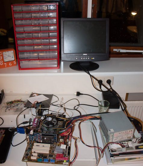
In this post I will explain how to flash bios chips with an Arduino. We will be using a Arduino Duemilnove (uno, mega or clones do also work) and a ASUS P5B motherboard that no longer boots after a failed bios update.
Here is an outline of the steps (some of these steps are not strictly necessary but I figured they might help the uninitiated):
- Identify board
- Find documentation for the board
- Locate and identify bios chip
- Find documentation for the chip
- Find pinout and operating voltages (important)
- Prepare the Arduino and installing flashrom
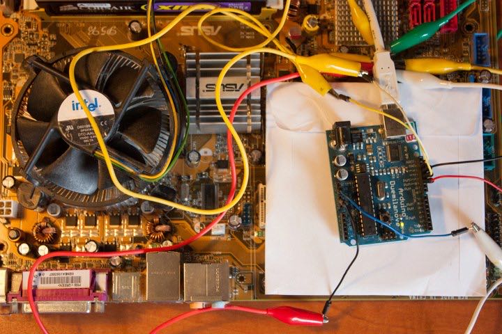
- Connecting the Arduino to the chip
- Testing
- Flashing and verify
- Troubleshooting
Identify board and finding documentation
As mentioned in the introduction we are using an ASUS P5B motherboard. The manual of this board can be found on the ASUS website (a direct link can be found in the list of references).
Locate and identifying the bios chip
In the manual we find a board layout that shows the location of the chip, to the right of pci slot 3.

In case the location is not documented we have to find it ourselves. The following page provides instructions on how to locate the bios chip: http://www.bios-chip24.com/Information/Bios-Chip-localization
The next step is to identify what brand and type of chip we are dealing with in order to find the datasheet. Usually the writing on the chip is everything we need as it states the manufacturer and model number. The motherboard manual mentions a “MXIC 25L8005” and if we look at the board we see that the model is indeed a 25L8005 made by Macronix.
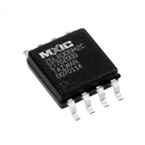
Typing the model number into google returns the datasheet as one of the first results. The information we are looking for is the pinout and operating voltage. The following image shows the pinout of the 25L8005:

The pin names do not make much sense if you are seeing them for the first time so the datasheet also include a description of the pin names:

For more information on what exactly the pins do please refer to the datasheet.
Preparing the Arduino
For the Arduino to be able to act as a serial programmer we need to first prepare it using frser-duino. The following command(s) will download and install the required packages, install flashrom, clone frser-duino and flash the Arduino.
sudo apt install git flashrom gcc-avr binutils-avr avr-libc avrdude
git clone --recursive https://github.com/tomvanveen/frser-duino.git
cd frser-duino
make ftdi
sudo make flash-ftdi
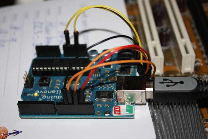
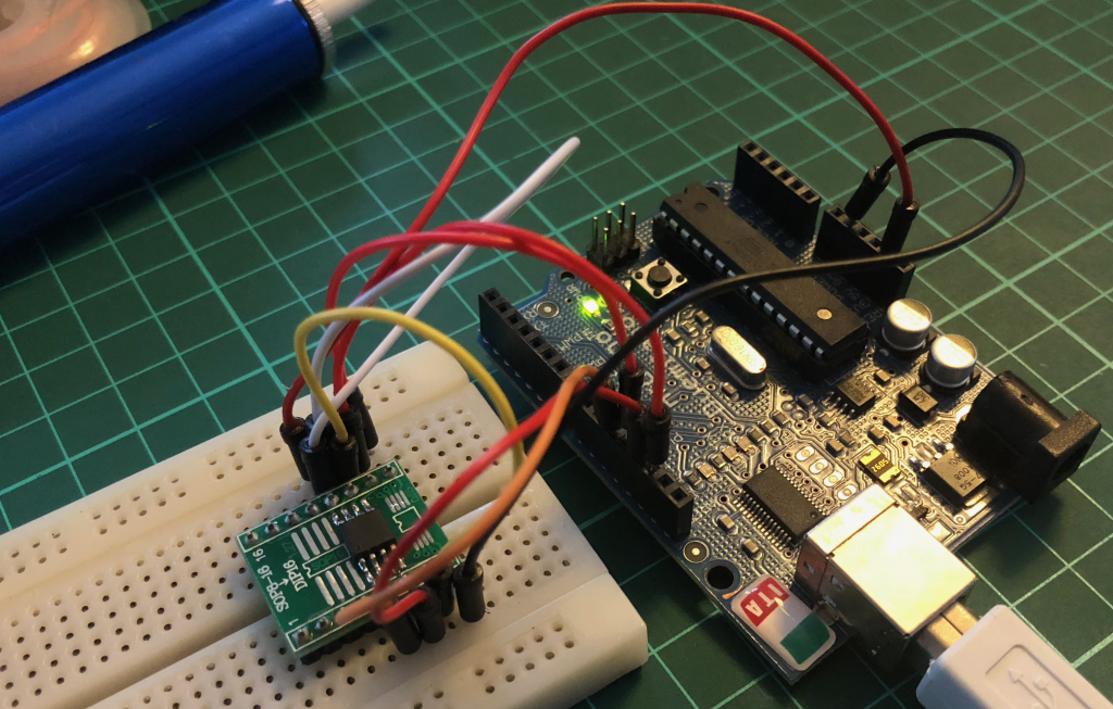
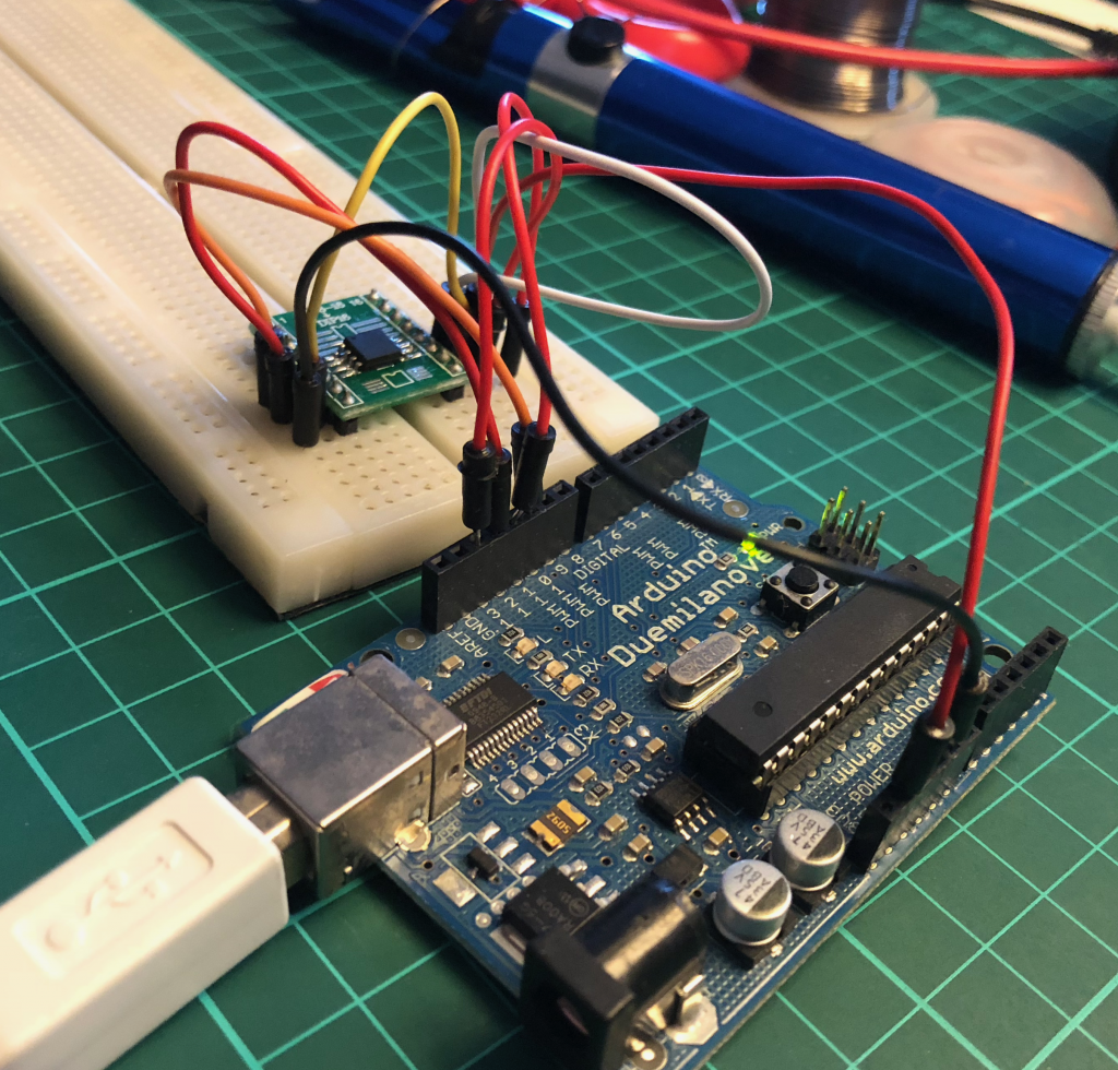
Connecting the Arduino to the SPI chip
The following image is an example schematic taken from the flashrom GitHub and shows the pins on the Arduino and the pins on the chip they should connect to (please note that PB0 does not have to be connected):
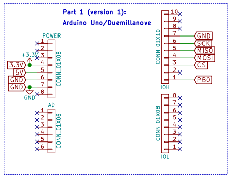
Emergency edit here: I know understand why people use resistors between the Arduino pins and the chip. The Arduino operates on 5V meaning its logic levels are also at 5V. This need to be brought down to 3.3v using a level shifter.
Flashing the SPI chip
To verify that everything is working correctly we first run flashrom without any operations:
sudo flashrom -p serprog:dev=/dev/ttyUSB0:2000000
The output should look like this:
flashrom v0.9.9-91-g0bfa819 on Linux 4.10.0-28-generic (x86_64)
flashrom is free software, get the source code at https://flashrom.org

Using clock_gettime for delay loops (clk_id: 1, resolution: 1ns).
serprog: Programmer name is "frser-duino"
Found Macronix flash chip "MX25L8005" (1024 kB, SPI) on serprog.
No operations were specified.
If the previous command worked as expected we are now ready for our final step. To write the new BIOS to the chip we use the following command:
sudo flashrom -p serprog:dev=/dev/ttyUSB0:2000000 -w [NEWBIOS]
The output should look like this:
flashrom v0.9.9-91-g0bfa819 on Linux 4.10.0-28-generic (x86_64) flashrom is free software, get the source code at https://flashrom.org Using clock_gettime for delay loops (clk_id: 1, resolution: 1ns). serprog: Programmer name is "frser-duino" Found Macronix flash chip "MX25L8005" (1024 kB, SPI) on serprog. Reading old flash chip contents... done. Erasing and writing flash chip... Erase/write done. Verifying flash... VERIFIED.
And that is it. We have successfully flashed a chip using the SPI interface. If you have any questions or feedback about this post please leave a comment below!
References
- The post that led me to start this project
- The instructions I used for this project
- 25L8005 datasheet
- Good discussion on the HP forum about recovering HP envy’s using this method

Wiring fail 1 
Wiring fail 2 Wiring fixed 
Fingers crossed! 
It boots! 
2018 Retry 1 
2018 Retry 2

Hi, I have an HP Mini with IIRC the 25C32 but apparently it will probably work with a larger chip. Has anyone managed to clone a BIOS this way, in order to use the extra space for a bootblock etc?
Hi,
Not that I know of.
What version of the HP mini do you have ( I cant find any HP mini with a 25C32 )?
Sorry my bad, its actually on a different HP.
The Mini uses a 16Mb (2MB) part.
Also it just failed completely due to an SSD install, never seen this happen before. Any ideas?
About the only change was to put the chip in a socket, so hopefully any repair should be slightly easier.
Hi! When I try to make I get this error:
alessio@alessio-VirtualBox:~/frser-duino > make u2 && make flash-u2
DFLAGS= FRBAUD=115200 make clean all
make[1]: Entering directory `/home/alessio/frser-duino’
rm -f frser-duino.bin
rm -f frser-duino.out
rm -f frser-duino.hex
rm -f frser-duino.s
rm -f *.o
avr-gcc -mmcu=atmega328p -DBAUD=115200 -Os -Wl,–relax -fno-inline-small-functions -fno-tree-switch-conversion -frename-registers -g -Wall -W -pipe -flto -fwhole-program -std=gnu99 -Ilibfrser -I. -o frser-duino.out main.c uart.c spihw.c libfrser/frser.c libfrser/udelay.c libfrser/spilib.c libfrser/spihw_avrspi.c
In function ‘__vector_18’:
uart.c:31:1: warning: ‘_vector_18’ appears to be a misspelled signal handler [enabled by default]
ISR(USART_RX_vect) {
^
avr-size frser-duino.out
text data bss dec hex filename
1370 0 1036 2406 966 frser-duino.out
make[1]: Leaving directory `/home/alessio/frser-duino’
BLBAUD=115200 SERIAL_DEV=/dev/ttyACM0 make program
make[1]: Entering directory `/home/alessio/frser-duino’
avr-objcopy -j .text -j .data -O ihex frser-duino.out frser-duino.hex
avrdude -c arduino -p m328p -P /dev/ttyACM0 -b 115200 -U flash:w:frser-duino.hex
avrdude: ser_open(): can’t open device “/dev/ttyACM0”: No such file or directory
ioctl(“TIOCMGET”): Invalid argument
avrdude done. Thank you.
make[1]: *** [program] Error 1
make[1]: Leaving directory `/home/alessio/frser-duino’
make: *** [flash-u2] Error 2
How to fix it?
Thanks in advance,
Alessio.
Hi Alessio,
What version Arduino do you have?
I’ve looked into this (I was using ubuntu 12.04 and vmware). Depending on your Arduino it will either be on /dev/ttyUSB0 or /dev/ttyACM0. I have a Chinese Uno which does not have the 8u2 chip but instead has a Chinese FTDI chip so it will show up as /dev/ttyUSB0. I had to alter the makefile to make sure the correct device was selected when using the make u2 command. Finally I had to upgrade ubuntu to 14.04 and install VMWare tools to fix a problem I had when using flashrom. Please let me know if this works for you.
Hello, Tom van Veen!
My arduino is also Chinese, as is yours. Because of this, initially, I decided to make the configuration the same as you did but so far it has not worked. I’ve used ‘u2’ and ‘ftdi’ mode; I already tried to modify the ‘Makefile’ as the ‘README.md’ explains … and finally, I’m already without imagination to know what I should do more.
Quando eu entro no Arduino, a porta USB que é detectada é “/dev/ttyUSB0”;
Quando uso o terminal Linux com o comando
“sudo flashrom -p serprog:dev=/dev/ttyACM0:115200”, no final aparece isso:
“Error: Cannot open serial port: No such file or directory
Error: Programmer initialization failed.”;
Quando “sudo flashrom -p serprog:dev=/dev/ttyUSB0:115200”, aparece no fim:
“Error: cannot synchronize protocol – check communications and reset device?
Error: Programmer initialization failed.”
Finally, I decided to post my comment here because you say that you had to change the ‘Makefile’ so that ‘u2’ would match the device.
Could you give me a hint on how I should make this change?
Thank you.
Wagner.
Hi Wagner,
I shall take a further look when I get home but is you type “ls /dev” with the Arduino connected do you see a device called ttyUSB0 or ttyACM0?
I typed “ls /dev” and as you can see appears “ttyUSB0”:
(I hit “enter” on purpose to focus)
[ wagner@kali:~$ ls /dev
autofs kmsg sdb1 tty17 tty4 tty62 vcsa3
block log sdb2 tty18 tty40 tty63 vcsa4
bsg loop-control sdc tty19 tty41 tty7 vcsa5
btrfs-control mapper sdc1 tty2 tty42 tty8 vcsa6
bus media0 sdc2 tty20 tty43 tty9 vcsa7
char mem serial tty21 tty44 ttyS0 vcsu
console midi sg0 tty22 tty45 ttyS1 vcsu1
core mqueue sg1 tty23 tty46 ttyS2 vcsu2
cpu_dma_latency net sg2 tty24 tty47 ttyS3 vcsu3
cuse null shm tty25 tty48 ttyUSB0 vcsu4
disk nvram snapshot tty26 tty49 uhid vcsu5
dmmidi port snd tty27 tty5 uinput vcsu6
dri ppp stderr tty28 tty50 urandom vcsu7
fb0 psaux stdin tty29 tty51 v4l vfio
fd ptmx stdout tty3 tty52 vcs vga_arbiter
full pts tty tty30 tty53 vcs1 vhci
fuse random tty0 tty31 tty54 vcs2 vhost-net
hidraw0 rfkill tty1 tty32 tty55 vcs3 vhost-vsock
hidraw1 rtc tty10 tty33 tty56 vcs4 video0
hidraw2 rtc0 tty11 tty34 tty57 vcs5 video1
hpet sda tty12 tty35 tty58 vcs6 watchdog
hugepages sda1 tty13 tty36 tty59 vcs7 watchdog0
hwrng sda2 tty14 tty37 tty6 vcsa zero
initctl sda5 tty15 tty38 tty60 vcsa1
input sdb tty16 tty39 tty61 vcsa2 ]
I want to take the opportunity to say that as I am from Brazil, I ended up forgetting the middle part of my first post without a translation into english; then goes the translated form:
[ When I run the Arduino IDE, the USB port that is detected is “/dev/ttyUSB0”;
When I use the Linux terminal with the command
“Sudo flashrom -p serprog: dev=/dev/ttyACM0:115200”, at the end it appears:
“Error: Cannot open serial port: No such file or directory
Error: Programmer initialization failed. ”;
When “sudo flashrom -p serprog:dev=/dev/ttyUSB0:115200”, it appears at the end:
“Error: cannot synchronize protocol – check communications and reset device?
Error: Programmer initialization failed. ” ]
######################################################
But now, I think is better to include else this information:
I alter the lines 87 (u2:) and 91 (flash-u2:) in the archive “Makefile” like this:
87 from this —> DFLAGS= FRBAUD=115200 $(MAKE) all
to —> DFLAGS=-DFTDI FRBAUD=115200 $(MAKE) all
(and)
91 from this —> BLBAUD=115200 SERIAL_DEV=/dev/ttyACM0 $(MAKE) program
to —> BLBAUD=115200 SERIAL_DEV=/dev/ttyUSB0 $(MAKE) program
trying to follow the instructions of “README.md”.
Then, in the terminal:
wagner@kali:~/frser-duino$ sudo make u2 && make flash-u2
[sudo] senha para wagner:
make clean
make[1]: Entering directory ‘/home/wagner/frser-duino’
rm -f frser-duino.bin
rm -f frser-duino.out
rm -f frser-duino.hex
rm -f frser-duino.s
rm -f *.o
make[1]: Leaving directory ‘/home/wagner/frser-duino’
DFLAGS=-DFTDI FRBAUD=115200 make all
make[1]: Entering directory ‘/home/wagner/frser-duino’
avr-gcc -mmcu=atmega328p -DBAUD=115200 -Os -fno-inline-small-functions -fno-tree-switch-conversion -frename-registers -g -Wall -W -pipe -flto -fwhole-program -std=gnu99 -DFTDI -Ilibfrser -std=gnu99 -I. -o frser-duino.out main.c uart.c spihw.c libfrser/frser.c libfrser/udelay.c libfrser/spilib.c libfrser/spihw_avrspi.c
avr-size frser-duino.out
text data bss dec hex filename
1418 0 1036 2454 996 frser-duino.out
make[1]: Leaving directory ‘/home/wagner/frser-duino’
BLBAUD=115200 SERIAL_DEV=/dev/ttyUSB0 make program
make[1]: Entering directory ‘/home/wagner/frser-duino’
avr-objcopy -j .text -j .data -O ihex frser-duino.out frser-duino.hex
avr-objcopy:frser-duino.hex: Permissão negada
make[1]: *** [Makefile:56: frser-duino.hex] Error 1
make[1]: Leaving directory ‘/home/wagner/frser-duino’
make: *** [Makefile:91: flash-u2] Error 2
###############################################
And,
wagner@kali:~/frser-duino$ sudo flashrom -p serprog:dev=/dev/ttyUSB0:115200
flashrom v1.2 on Linux 5.6.0-kali1-686-pae (i686)
flashrom is free software, get the source code at https://flashrom.org
Using clock_gettime for delay loops (clk_id: 1, resolution: 1ns).
Error: cannot synchronize protocol – check communications and reset device?
Error: Programmer initialization failed.
Again,
wagner@kali:~/frser-duino$ sudo flashrom -p serprog:dev=/dev/ttyUSB0:2000000
flashrom v1.2 on Linux 5.6.0-kali1-686-pae (i686)
flashrom is free software, get the source code at https://flashrom.org
Using clock_gettime for delay loops (clk_id: 1, resolution: 1ns).
Error: cannot synchronize protocol – check communications and reset device?
Error: Programmer initialization failed.
###############################################
Others information:
The BIOS in which I am working is (Winbond) 25Q32BVAIG, from an Asus desktop. “PIH61 Series”.
That is it, for while…
Hi Wagner, tudo bem? 🙂
From the information you shared with me I understand your Arduino is showing up under ttyUSB0. I also spot you get a permission denied (Permissão negada) when flashing the Arduino, this is because you are not running “make flash-u2” with sudo. Could you share the make and or model of the Arduino you are using, maybe upload a picture to imgur?
Hi, good morning!
As you said in your last massage:
####################################################
Tom van Veensays:
2 June 2020 at 20:52
Hi Wagner, tudo bem?
From the information you shared with me I understand your Arduino is showing up under ttyUSB0. I also spot you get a permission denied (Permissão negada) when flashing the Arduino, this is because you are not running “make flash-u2” with sudo. Could you share the make and or model of the Arduino you are using, maybe upload a picture to imgur?
####################################################
And as there doesn’t have a “reply” button, I came back to here for answer it.
Before, I want to remember that I had said that I would try the procedures through a Linux system installed on a pendrive … but sometime this morning I realized that maybe I could succeed if I typed “sudo su” in the terminal and not just “sudo” and to my positive surprise, yes, it was just that! So I started to copy one piece at a time, but after all, I decided to copy exactly EVERYTHING and post it here, so it gets better clarified. But first, I also want to let you know that at one point I tested with 2000000 bauds speed but there was no sync, so I could be sure that the right format is with 115200! Some others thing is that although I had used “sudo su”, after that I yet used “sudo” that I thing it wasn’t necessary; I also used the command: “git clone –recursive git://github.com/urjaman/frser-duino” but I don’t have sure if it was really necessary; I named the file with the name of my client, but now, I realized that a good option is the same name of the chip, “w25q32” or something like this, in my case. Finally, this was just a confirmation of the recorder’s functionality and also to guarantee a copy of the original BIOS, but I still need to confirm if for this PC there is already a newer BIOS.
Okay, so see the result:
####################################################
wagner@kali:~/frser-duino$ sudo su make u2 && make flash-u2
su: user make does not exist or the user entry does not contain all the required fields
wagner@kali:~/frser-duino$ sudo su
root@kali:/home/wagner/frser-duino# sudo make u2 && make flash-u2
make clean
make[1]: Entering directory ‘/home/wagner/frser-duino’
rm -f frser-duino.bin
rm -f frser-duino.out
rm -f frser-duino.hex
rm -f frser-duino.s
rm -f *.o
make[1]: Leaving directory ‘/home/wagner/frser-duino’
DFLAGS=-DFTDI FRBAUD=115200 make all
make[1]: Entering directory ‘/home/wagner/frser-duino’
avr-gcc -mmcu=atmega328p -DBAUD=115200 -Os -fno-inline-small-functions -fno-tree-switch-conversion -frename-registers -g -Wall -W -pipe -flto -fwhole-program -std=gnu99 -DFTDI -Ilibfrser -std=gnu99 -I. -o frser-duino.out main.c uart.c spihw.c libfrser/frser.c libfrser/udelay.c libfrser/spilib.c libfrser/spihw_avrspi.c
avr-size frser-duino.out
text data bss dec hex filename
1418 0 1036 2454 996 frser-duino.out
make[1]: Leaving directory ‘/home/wagner/frser-duino’
BLBAUD=115200 SERIAL_DEV=/dev/ttyUSB0 make program
make[1]: Entering directory ‘/home/wagner/frser-duino’
avr-objcopy -j .text -j .data -O ihex frser-duino.out frser-duino.hex
avrdude -c arduino -p m328p -P /dev/ttyUSB0 -b 115200 -U flash:w:frser-duino.hex
avrdude: AVR device initialized and ready to accept instructions
Reading | ################################################## | 100% 0.00s
avrdude: Device signature = 0x1e950f (probably m328p)
avrdude: NOTE: “flash” memory has been specified, an erase cycle will be performed
To disable this feature, specify the -D option.
avrdude: erasing chip
avrdude: reading input file “frser-duino.hex”
avrdude: input file frser-duino.hex auto detected as Intel Hex
avrdude: writing flash (1418 bytes):
Writing | ################################################## | 100% 0.27s
avrdude: 1418 bytes of flash written
avrdude: verifying flash memory against frser-duino.hex:
avrdude: load data flash data from input file frser-duino.hex:
avrdude: input file frser-duino.hex auto detected as Intel Hex
avrdude: input file frser-duino.hex contains 1418 bytes
avrdude: reading on-chip flash data:
Reading | ################################################## | 100% 0.21s
avrdude: verifying …
avrdude: 1418 bytes of flash verified
avrdude: safemode: Fuses OK (E:00, H:00, L:00)
avrdude done. Thank you.
make[1]: Leaving directory ‘/home/wagner/frser-duino’
root@kali:/home/wagner/frser-duino# git clone –recursive git://github.com/urjaman/frser-duino
Cloning into ‘frser-duino’…
remote: Enumerating objects: 363, done.
remote: Total 363 (delta 0), reused 0 (delta 0), pack-reused 363
Receiving objects: 100% (363/363), 101.32 KiB | 857.00 KiB/s, done.
Resolving deltas: 100% (242/242), done.
Submodule ‘libfrser’ (https://github.com/urjaman/libfrser.git) registered for path ‘libfrser’
Cloning into ‘/home/wagner/frser-duino/frser-duino/libfrser’…
remote: Enumerating objects: 408, done.
remote: Total 408 (delta 0), reused 0 (delta 0), pack-reused 408
Receiving objects: 100% (408/408), 123.07 KiB | 458.00 KiB/s, done.
Resolving deltas: 100% (271/271), done.
Submodule path ‘libfrser’: checked out ‘a628f1961a6b83a3f135aa47fbf7078da89018cd’
root@kali:/home/wagner/frser-duino# flashrom -p serprog:dev=/dev/ttyUSB0:2000000
flashrom v1.2 on Linux 5.6.0-kali1-686-pae (i686)
flashrom is free software, get the source code at https://flashrom.org
Using clock_gettime for delay loops (clk_id: 1, resolution: 1ns).
Error: cannot synchronize protocol – check communications and reset device?
Error: Programmer initialization failed.
root@kali:/home/wagner/frser-duino# sudo flashrom -p serprog:dev=/dev/ttyUSB0:115200
flashrom v1.2 on Linux 5.6.0-kali1-686-pae (i686)
flashrom is free software, get the source code at https://flashrom.org
Using clock_gettime for delay loops (clk_id: 1, resolution: 1ns).
serprog: Programmer name is “frser-duino”
serprog: requested mapping AT45CS1282 is incompatible: 0x1080000 bytes at 0xfef80000.
serprog: requested mapping GD25Q256D is incompatible: 0x2000000 bytes at 0xfe000000.
serprog: requested mapping IS25LP256 is incompatible: 0x2000000 bytes at 0xfe000000.
serprog: requested mapping IS25WP256 is incompatible: 0x2000000 bytes at 0xfe000000.
serprog: requested mapping MX25L25635F/MX25L25645G is incompatible: 0x2000000 bytes at 0xfe000000.
serprog: requested mapping MX25U25635F is incompatible: 0x2000000 bytes at 0xfe000000.
serprog: requested mapping MX25U51245G is incompatible: 0x4000000 bytes at 0xfc000000.
serprog: requested mapping MX66L51235F/MX25L51245G is incompatible: 0x4000000 bytes at 0xfc000000.
serprog: requested mapping N25Q00A..1G is incompatible: 0x8000000 bytes at 0xf8000000.
serprog: requested mapping N25Q00A..3G is incompatible: 0x8000000 bytes at 0xf8000000.
serprog: requested mapping N25Q256..1E is incompatible: 0x2000000 bytes at 0xfe000000.
serprog: requested mapping N25Q256..3E is incompatible: 0x2000000 bytes at 0xfe000000.
serprog: requested mapping N25Q512..1G is incompatible: 0x4000000 bytes at 0xfc000000.
serprog: requested mapping N25Q512..3G is incompatible: 0x4000000 bytes at 0xfc000000.
serprog: requested mapping MT25QL01G is incompatible: 0x8000000 bytes at 0xf8000000.
serprog: requested mapping MT25QU01G is incompatible: 0x8000000 bytes at 0xf8000000.
serprog: requested mapping MT25QL02G is incompatible: 0x10000000 bytes at 0xf0000000.
serprog: requested mapping MT25QU02G is incompatible: 0x10000000 bytes at 0xf0000000.
serprog: requested mapping MT25QL256 is incompatible: 0x2000000 bytes at 0xfe000000.
serprog: requested mapping MT25QU256 is incompatible: 0x2000000 bytes at 0xfe000000.
serprog: requested mapping MT25QL512 is incompatible: 0x4000000 bytes at 0xfc000000.
serprog: requested mapping MT25QU512 is incompatible: 0x4000000 bytes at 0xfc000000.
serprog: requested mapping S25FL256S……0 is incompatible: 0x2000000 bytes at 0xfe000000.
serprog: requested mapping S25FL512S is incompatible: 0x4000000 bytes at 0xfc000000.
serprog: requested mapping W25Q256.V is incompatible: 0x2000000 bytes at 0xfe000000.
serprog: requested mapping W25Q256JV_M is incompatible: 0x2000000 bytes at 0xfe000000.
Found Winbond flash chip “W25Q32.V” (4096 kB, SPI) on serprog.
No operations were specified.
root@kali:/home/wagner/frser-duino# sudo flashrom -p serprog:dev=/dev/ttyUSB0:2000000
flashrom v1.2 on Linux 5.6.0-kali1-686-pae (i686)
flashrom is free software, get the source code at https://flashrom.org
Using clock_gettime for delay loops (clk_id: 1, resolution: 1ns).
Error: cannot synchronize protocol – check communications and reset device?
Error: Programmer initialization failed.
root@kali:/home/wagner/frser-duino# sudo flashrom -p serprog:dev=/dev/ttyUSB0:115200
flashrom v1.2 on Linux 5.6.0-kali1-686-pae (i686)
flashrom is free software, get the source code at https://flashrom.org
Using clock_gettime for delay loops (clk_id: 1, resolution: 1ns).
serprog: Programmer name is “frser-duino”
serprog: requested mapping AT45CS1282 is incompatible: 0x1080000 bytes at 0xfef80000.
serprog: requested mapping GD25Q256D is incompatible: 0x2000000 bytes at 0xfe000000.
serprog: requested mapping IS25LP256 is incompatible: 0x2000000 bytes at 0xfe000000.
serprog: requested mapping IS25WP256 is incompatible: 0x2000000 bytes at 0xfe000000.
serprog: requested mapping MX25L25635F/MX25L25645G is incompatible: 0x2000000 bytes at 0xfe000000.
serprog: requested mapping MX25U25635F is incompatible: 0x2000000 bytes at 0xfe000000.
serprog: requested mapping MX25U51245G is incompatible: 0x4000000 bytes at 0xfc000000.
serprog: requested mapping MX66L51235F/MX25L51245G is incompatible: 0x4000000 bytes at 0xfc000000.
serprog: requested mapping N25Q00A..1G is incompatible: 0x8000000 bytes at 0xf8000000.
serprog: requested mapping N25Q00A..3G is incompatible: 0x8000000 bytes at 0xf8000000.
serprog: requested mapping N25Q256..1E is incompatible: 0x2000000 bytes at 0xfe000000.
serprog: requested mapping N25Q256..3E is incompatible: 0x2000000 bytes at 0xfe000000.
serprog: requested mapping N25Q512..1G is incompatible: 0x4000000 bytes at 0xfc000000.
serprog: requested mapping N25Q512..3G is incompatible: 0x4000000 bytes at 0xfc000000.
serprog: requested mapping MT25QL01G is incompatible: 0x8000000 bytes at 0xf8000000.
serprog: requested mapping MT25QU01G is incompatible: 0x8000000 bytes at 0xf8000000.
serprog: requested mapping MT25QL02G is incompatible: 0x10000000 bytes at 0xf0000000.
serprog: requested mapping MT25QU02G is incompatible: 0x10000000 bytes at 0xf0000000.
serprog: requested mapping MT25QL256 is incompatible: 0x2000000 bytes at 0xfe000000.
serprog: requested mapping MT25QU256 is incompatible: 0x2000000 bytes at 0xfe000000.
serprog: requested mapping MT25QL512 is incompatible: 0x4000000 bytes at 0xfc000000.
serprog: requested mapping MT25QU512 is incompatible: 0x4000000 bytes at 0xfc000000.
serprog: requested mapping S25FL256S……0 is incompatible: 0x2000000 bytes at 0xfe000000.
serprog: requested mapping S25FL512S is incompatible: 0x4000000 bytes at 0xfc000000.
serprog: requested mapping W25Q256.V is incompatible: 0x2000000 bytes at 0xfe000000.
serprog: requested mapping W25Q256JV_M is incompatible: 0x2000000 bytes at 0xfe000000.
Found Winbond flash chip “W25Q32.V” (4096 kB, SPI) on serprog.
No operations were specified.
root@kali:/home/wagner/frser-duino# flashrom -p serprog:dev=/dev/ttyUSB0:115200 -r adriano.rom
flashrom v1.2 on Linux 5.6.0-kali1-686-pae (i686)
flashrom is free software, get the source code at https://flashrom.org
Using clock_gettime for delay loops (clk_id: 1, resolution: 1ns).
serprog: Programmer name is “frser-duino”
serprog: requested mapping AT45CS1282 is incompatible: 0x1080000 bytes at 0xfef80000.
serprog: requested mapping GD25Q256D is incompatible: 0x2000000 bytes at 0xfe000000.
serprog: requested mapping IS25LP256 is incompatible: 0x2000000 bytes at 0xfe000000.
serprog: requested mapping IS25WP256 is incompatible: 0x2000000 bytes at 0xfe000000.
serprog: requested mapping MX25L25635F/MX25L25645G is incompatible: 0x2000000 bytes at 0xfe000000.
serprog: requested mapping MX25U25635F is incompatible: 0x2000000 bytes at 0xfe000000.
serprog: requested mapping MX25U51245G is incompatible: 0x4000000 bytes at 0xfc000000.
serprog: requested mapping MX66L51235F/MX25L51245G is incompatible: 0x4000000 bytes at 0xfc000000.
serprog: requested mapping N25Q00A..1G is incompatible: 0x8000000 bytes at 0xf8000000.
serprog: requested mapping N25Q00A..3G is incompatible: 0x8000000 bytes at 0xf8000000.
serprog: requested mapping N25Q256..1E is incompatible: 0x2000000 bytes at 0xfe000000.
serprog: requested mapping N25Q256..3E is incompatible: 0x2000000 bytes at 0xfe000000.
serprog: requested mapping N25Q512..1G is incompatible: 0x4000000 bytes at 0xfc000000.
serprog: requested mapping N25Q512..3G is incompatible: 0x4000000 bytes at 0xfc000000.
serprog: requested mapping MT25QL01G is incompatible: 0x8000000 bytes at 0xf8000000.
serprog: requested mapping MT25QU01G is incompatible: 0x8000000 bytes at 0xf8000000.
serprog: requested mapping MT25QL02G is incompatible: 0x10000000 bytes at 0xf0000000.
serprog: requested mapping MT25QU02G is incompatible: 0x10000000 bytes at 0xf0000000.
serprog: requested mapping MT25QL256 is incompatible: 0x2000000 bytes at 0xfe000000.
serprog: requested mapping MT25QU256 is incompatible: 0x2000000 bytes at 0xfe000000.
serprog: requested mapping MT25QL512 is incompatible: 0x4000000 bytes at 0xfc000000.
serprog: requested mapping MT25QU512 is incompatible: 0x4000000 bytes at 0xfc000000.
serprog: requested mapping S25FL256S……0 is incompatible: 0x2000000 bytes at 0xfe000000.
serprog: requested mapping S25FL512S is incompatible: 0x4000000 bytes at 0xfc000000.
serprog: requested mapping W25Q256.V is incompatible: 0x2000000 bytes at 0xfe000000.
serprog: requested mapping W25Q256JV_M is incompatible: 0x2000000 bytes at 0xfe000000.
Found Winbond flash chip “W25Q32.V” (4096 kB, SPI) on serprog.
Reading flash… done.
root@kali:/home/wagner/frser-duino# flashrom -p serprog:dev=/dev/ttyUSB0:115200 -W adriano.rom
flashrom v1.2 on Linux 5.6.0-kali1-686-pae (i686)
flashrom is free software, get the source code at https://flashrom.org
flashrom: invalid option — ‘W’
Please run “flashrom –help” for usage info.
root@kali:/home/wagner/frser-duino# flashrom -p serprog:dev=/dev/ttyUSB0:115200 -w adriano.rom
flashrom v1.2 on Linux 5.6.0-kali1-686-pae (i686)
flashrom is free software, get the source code at https://flashrom.org
Using clock_gettime for delay loops (clk_id: 1, resolution: 1ns).
serprog: Programmer name is “frser-duino”
serprog: requested mapping AT45CS1282 is incompatible: 0x1080000 bytes at 0xfef80000.
serprog: requested mapping GD25Q256D is incompatible: 0x2000000 bytes at 0xfe000000.
serprog: requested mapping IS25LP256 is incompatible: 0x2000000 bytes at 0xfe000000.
serprog: requested mapping IS25WP256 is incompatible: 0x2000000 bytes at 0xfe000000.
serprog: requested mapping MX25L25635F/MX25L25645G is incompatible: 0x2000000 bytes at 0xfe000000.
serprog: requested mapping MX25U25635F is incompatible: 0x2000000 bytes at 0xfe000000.
serprog: requested mapping MX25U51245G is incompatible: 0x4000000 bytes at 0xfc000000.
serprog: requested mapping MX66L51235F/MX25L51245G is incompatible: 0x4000000 bytes at 0xfc000000.
serprog: requested mapping N25Q00A..1G is incompatible: 0x8000000 bytes at 0xf8000000.
serprog: requested mapping N25Q00A..3G is incompatible: 0x8000000 bytes at 0xf8000000.
serprog: requested mapping N25Q256..1E is incompatible: 0x2000000 bytes at 0xfe000000.
serprog: requested mapping N25Q256..3E is incompatible: 0x2000000 bytes at 0xfe000000.
serprog: requested mapping N25Q512..1G is incompatible: 0x4000000 bytes at 0xfc000000.
serprog: requested mapping N25Q512..3G is incompatible: 0x4000000 bytes at 0xfc000000.
serprog: requested mapping MT25QL01G is incompatible: 0x8000000 bytes at 0xf8000000.
serprog: requested mapping MT25QU01G is incompatible: 0x8000000 bytes at 0xf8000000.
serprog: requested mapping MT25QL02G is incompatible: 0x10000000 bytes at 0xf0000000.
serprog: requested mapping MT25QU02G is incompatible: 0x10000000 bytes at 0xf0000000.
serprog: requested mapping MT25QL256 is incompatible: 0x2000000 bytes at 0xfe000000.
serprog: requested mapping MT25QU256 is incompatible: 0x2000000 bytes at 0xfe000000.
serprog: requested mapping MT25QL512 is incompatible: 0x4000000 bytes at 0xfc000000.
serprog: requested mapping MT25QU512 is incompatible: 0x4000000 bytes at 0xfc000000.
serprog: requested mapping S25FL256S……0 is incompatible: 0x2000000 bytes at 0xfe000000.
serprog: requested mapping S25FL512S is incompatible: 0x4000000 bytes at 0xfc000000.
serprog: requested mapping W25Q256.V is incompatible: 0x2000000 bytes at 0xfe000000.
serprog: requested mapping W25Q256JV_M is incompatible: 0x2000000 bytes at 0xfe000000.
Found Winbond flash chip “W25Q32.V” (4096 kB, SPI) on serprog.
Reading old flash chip contents… done.
Erasing and writing flash chip…
Warning: Chip content is identical to the requested image.
Erase/write done.
root@kali:/home/wagner/frser-duino#
####################################################
Final considerations:
As for the time taken for each procedure, in this case where the BIOS file is 4MB, all actions took around 6 minutes. In my opinion, for the speed of 115200 which is considered slow, it’s more than good! (the greater the slowness, the greater the fidelity of the copied data … “although this sounds like a joke, but it makes sense!”) Later, I will check the possibility of implementing the “fast-usbserial”.
Thank you for your help!
Wagner.
Happy to help!
hi.. I am using msi p67a-gd65. the bios is bricked. and it is in an infinite boot loop mode. I was going to do the things listed here but I am not really sure on what to do because the “how to do” issues are without any visual illustrations therefore I am easily lost on what to do. Am I able to do that on windows? or I need ubuntu specificaly to apply it? and is there a video or more pictures available ? so an amateur like me won’t get lost while trying to do it. I really appreciate your help.
Hi Mehmet,
If you are not able to follow the howto without extra information I would suggest sending your motherboard to someone who can repair it for you.
Kinds regards,
Tom
Dear Tom.
My name is Pavlo and I am trying to fix my HP motherboard using this instruction:
http://h30434.www3.hp.com/t5/Desktop-Hardware-and-Upgrade-Questions/HP-Envy-23-AIO-No-Beep-Screen-Blank-No-USB/td-p/4923733/page/2
But the terminal is saying “Error: Cannot open serial port: Permission denied”
“Error: Programmer initialization failed”
Hi Pavlo,
As what user are you trying to run the program in terminal?
Kind regards,
Tom
Hi, unfortunately there is nothing said about the resistors if using the SPI header. But in the hardware part there are mentioned three of them, are they for the signal lines to reduce the voltage of the high level? I want to try flashing the bios on a MSI z77a-g45 with an arduino micro..
Hi,
I did not use any resistors during this project as they were not needed. The flashrom website I linked to below the post does speak of resistors for getting the correct voltage (5v or 3.3v). Ultimately it will depend on the kind of chip you are flashing.
Hi Tom,
thanks for your reply!
I missed the link of the flashrom website about the arduino flasher, even though I browsed them for software reasons. Things are clear now, and my winbond 25Q64 chip can withstand VCC + 0.4 v and with a max VCC of 4.6 v it may work without resistors. Nevertheless I do not want to risk that and will built up level translation..
Kind regards
Lorenz
Hi Lorenz,
No problem! First time I get a response after giving a reply :D. To be honest I did not bother with the resistors because I’m kinda lazy. Luckily for me it worked perfectly. Will edit my post to mention the fact I did not use the resistors. Please let me know if you succeed with flashing your bios.
Kind regards,
Tom
Hi Tom,
I gave up trying to use my arduino micro, because its not supported by the serprog/frser-duino project! I did some research about that, but it looks like nobody is using a arduino micro to do rom flashing. The problem is, that the usb-to-serial bridge has moved in to the atmega32u4 chip on the arduino micro and it doesn’t look like there is an option in the flashrom program to use this kind of microcontroller.
Good thing is, I get my mainboard working again using a LPT-to-SPI adapter according to this tutorial:
http://rayer.g6.cz/elektro/spipgm.htm
https://blah.cloud/hardware/fix-broken-motherboard/
Now I am looking forward to find a solution without this outmoded LPT port. Maybe one day I have no PC left with a LPT port! But flashrom supports flashing via a raspberry pi and that looks great for me..
Kind regards,
Lorenz
Hi Lorenz,
Yeah its a bummer that your Arduino is not supported. You can always buy one that is supported by flashrom :). My first attempt was with the LPT to SPI adapter/cable but I could not get it to work and I shelved the project. When I read about using the arduino I decided it was time to try again.
Hello,
I have a issue while using the make flash-u2. In fact, i have this error:
avrdude: stk500_recv(): programmer is not responding
avrdude: stk500_getsync() attenmpt 1 of 10: not in sync: resp=0x00.
I’m using a mega 2560 and a VM of Lubuntu.
can you help me please ?
A.Murat
Hi,
I can not do much with the information you are giving me.
Can you maybe give me some info on the steps you’ve taken?
Kind regards,
Tom
i’m getting this same error, how did you fix it?
You can also use the -v (–verify) flag, which re-reads the flash contents and compares with the given file.
Thanks for the additional info! If you don’t mind I will add this to the post.
hi,
I have a problem. i did everything as you instructed. the first problem i came into was when i tried to read the bios chip which is MX25L1605D. the Error was cannot open serial port: permission denied. i searched around and found out that i need to chagne user. with this command
sudo usermod -a -G dialout
sudo chmod a+rw /dev/ttyACM0 (for uno r3) or ttyUSB0 (for nano with ftdi chip)
then i was able to follow the read command but on arduino uno it says
“Calibrating delay loop… OK.
serprog: Programmer name is “frser-duino”
Found Macronix flash chip “MX25L1605D/MX25L1608D/MX25L1673E” (2048 kB, SPI) on serprog.
Reading flash… Error: invalid response 0x90 from device (to command 0x13)
Read operation failed!
FAILED.
Error: invalid response 0xF5 from device (to command 0x15)
serprog: serprog_shutdown: Warning: could not disable output buffers
”
and on arduino nano it is just stuck on “reading flash” and doesnt go further
can you please help.
Hi Ali,
The permission error is likely because you are not running the program as root or any other privileged user.
From what I can gather the chip is detected but does not give the response expected by Flashrom.
Could you give more information on: how you connected the wires and if you used the resistors or not?
Kind regards,
Tom
Hi Tom. I have the same problem as Ali. I get to the point where it detects the chip but is stuck at “reading flash contents…”. I connected the pins as below and did not use resistor:
[Header Pins] [Arduino Pins]
———————————–
[1] VCC (3.3V in my case)[5V]
[3] SO(MISO,DO)[12]
[4] SI(MOSI,DIO)[11]
[5] CS#(SS)[10]
[6] SCLK(CLK,SCK)[13]
[7] GND[GND]
I have an Arduino ATMEGA328P board. It is detected as dev/ttyUSB0.
Using 3.3V does not detect the port at all but when I connected to 5V, it detects the USB0.
One thing I am curious is that, on the Arduino board, there are 2 other GND pins opposite the numbered pins (10, 11, 12, etc.). Same row as the 3.3V and 5V. Wondering if I should connect the GND header pin to either one of these Power GND pins in Arduino. Currently it’s connected to the GND next to Pin [13]. Thanks and would appreciate any help.
Elmer
Hi Elmer,
I don’t own a Mega but I assume using another GND pin will not solve your issue.
Are you using the software branch for the normal Arduino or the Mega?
Kind regards,
Tom
When you say software branch, do you mean the board’s driver? Initially, I used the driver my mega came with. I got the driver from this website:
http://www.wch.cn/download/CH341SER_LINUX_ZIP.html
It is only good for Kernel versions 2.6.25 to 3.13.x which is up to Ubuntu 12.04. Board is recognized but got the result above. Gets stuck at “Reading flash..”.
I upgraded to Ubuntu 14.04 and this time did not use the drivers with the board but somehow it is still recognized as USB0 so I figure it must be from my Arduino IDE installation that it gets recognized. Same result though. Moved cables to other GND and still get the same result. Might get a Raspberry Pi where some people have more success but I am just too close at this, it might just be something I am missing. Thanks anyhow. I will keep researching as someone might have experienced the same thing.
Elmer
I mean the software branche for seprog or fsrduino.
When you go here https://www.flashrom.org/Serprog/Arduino_flasher#Building_for_the_Mega1280_or_2560 it will say something about that the Arduino mega needs another version of the software.
I am using the normal branch for Arduino as it builds successfully using that branch only using “make u2 && make flash-u2”. I tried all the other branches and it doesn’t get a response.
Did you use the following command as instructed by the arduino flasher page: “$ git clone –recursive git://github.com/urjaman/frser-duino -b arduino-mega-1280” ?
done with raspberry pi 3 debian jessie and arduino uno. Its works thanks… 😀
pi@Sasikirana ~/flashrom $ ./flashrom -p serprog:dev=/dev/ttyACM0:115200 -w P5KPL-EPU-0404.ROM
flashrom v0.9.9-r1954 on Linux 4.4.36-v7+ (armv7l)
flashrom is free software, get the source code at https://flashrom.org
Calibrating delay loop… OK.
serprog: Programmer name is “frser-duino”
serprog: requested mapping AT45CS1282 is incompatible: 0x1080000 bytes at 0xfef80000.
Found Macronix flash chip “MX25L8005/MX25L8006E/MX25L8008E/MX25V8005” (1024 kB, SPI) on serprog.
Reading old flash chip contents… done.
Erasing and writing flash chip… Erase/write done.
Verifying flash… VERIFIED.
Nice!
Do you by any chance have a photo of your flashing setup? 😀
Kind regards,
Tom
Sory i dont have, i forgot to make screen shot my phone with juice ssh.
I flash using command from ssh over my xiaomi phone. my computer die coz corupt bios, nothing change, just follow the instruction from article.
fist time i don know how to flash it, if i buy bios flasher its make me spent extra money, so i think debian on raspi 3 or b+ can do it. its no thing to lose if fail (i assume bios broken) so must buy new one) so i try it.
this my step
download all library to my home dir on raspi debian weze, were its have mono, gcc, python (i have install homegenie smarthome, u can see on http://www.homegenie.it/)
– sudo apt-get install flashrom gcc-avr binutils-avr gdb-avr avr-libc avrdude git
– sudo git clone –recursive https://github.com/flashrom/flashrom.git
– cd flashrom
– then compile it with command make (look on flashrom instruction, coz some time u need to istall another library, on my case all ready no error on compile it)
– then i download the flasher arduino
sudo git clone –recursive git://github.com/urjaman/frser-duino
– cd frser-duino
– make u2 && make flash-u2
– i see 2 new file
frser-duino.out and frser-duino.hex
copy or move it to folder flashrom
mv frser-duino.out /home/pi/flashrom
mv frser-duino.hex /home/pi/flashrom
– then go to flashrom folder
cd /home/pi/flashrom
– download rom asus p5kpl with wget, extact it
– then i get ot bios from mainboard to project board, wiring it with my uno
[pin1 of the bios chip] /CS VCC 3.3V
[pin1 of the bios chip] /CSArduino pin10(SS, PORTB2)
[pin2 of the bios chip] DOArduino pin12(MISO, PORTB4)
[pin3 of the bios chip] /WPVCC 5V
[pin4 of the bios chip] GNDGND on the power pins
[pin8 of the bios chip] VCC+3.3V on the power pins of the Arduino
[pin7 of the bios chip] /HOLDVCC 3.3V
[pin6 of the bios chip] CLKArduino pin13(SCK, PORTB5)
[pin5 of the bios chip] DIOArduino pin11(MOSI, PORTB3)
– connect raspi to uno via usb, i push reset button on my uno
– then flash it
./flashrom -p serprog:dev=/dev/ttyACM0:115200 -w P5KPL-EPU-0404.ROM
sow message bla bla bla VERIFIED
– then i get back thts bios chip to my mainboard
– viola now i can write this message from my pc again 😀
Thanks for the info and congrats on getting it to work! 😀
I follow steps posted by you. And successfully write my rom. On desktop Debian
* Install flashrom (apt install falshrom)
*git clone –recursive https://github.com/flashrom/flashrom.git
*make u2
* make flash-u2 don’t work because the port is different. Then run averdude manually
* I use RED LED for level shift, RED LED have 1,78v drop voltage. and one 470 ohm to ground.. Better is to use RED LED and 1N4148 (small signal diode) in anti parallel, and nothing to ground. (at this time, I don’t have 1N4148)
https://drive.google.com/file/d/164IFm4IOmQ-T6zT0E-3KNo6kXeIJrTpL/view?usp=sharing
* I solder bottom up on pins over protoboard https://drive.google.com/file/d/1JEypnzbHkr6-dUEzddZrSB-xkePhR2us/view?usp=sharing
*This is the connection to arduino uno
https://drive.google.com/file/d/1Z_gzxM5A1vfI3wrBql1mF1wmZxqdnK2v/view?usp=sharing
*This is the screen shot of flashrom:
https://drive.google.com/file/d/1Z_gzxM5A1vfI3wrBql1mF1wmZxqdnK2v/view?usp=sharing
Forget to mention. I use arduino uno CH340 and the memory is one Windbond 25Q32.
Sorry
Awesome! Good to hear you got it to work.
Hello,
After a while of solving problems, I got to a problem which i can’t solve. Someone above had same issue – i got stuck on “Reading old flash chip contents…”
I use chinesse nano, and I’m trying to flash Winbond W25Q80 chip, it’s from asus motherboard. If it matters, only green led i lightning with a still green light. Any kind of idea what to do? ;-;
Hi Patrick, we (me and maybe some other commenters) need some more info on what steps you took so far. It also good to know how you connected the arduino to the chip etc.
Kind regards,
Tom
Tomordów I will be back in my house, and I will take pictures and etc. 🙂
Hi,
I need to reflash my M4N68T-M LE V2 motherboard’s BIOS chip. It uses cFeon EN25F80 chip, which is listed as working with this method. I previously had troubles programming my Geekcreit Arduino (uses Atmel ATMEGA328P), but that I got working. After some research I found that my Arduino is on dev=/dev/ttyACM0:115200, so I successfully addressed the Arduino. But while running flashrom I got errors:
Calibrating delay loop… OK.
serprog: Programmer name is “frser-duino”
serprog: requested mapping AT45CS1282 is incompatible: 0x1080000 bytes at 0xfef80000 .
No EEPROM/flash device found.
Note: flashrom can never write if the flash chip isn’t found automatically.
I checked the wiring, I even rewired it, then rewired it using resistor divider method described on flashrom.org. Still same result.
Thanks for any suggestions.
Kind regards,
Franta
Hi, so it seems Flashrom does not see the chip. Could you upload a picture showing how you connected the Arduino to the chip? Any other information is also welcome :).
I am not very proud of this… umm… contraption? (I don’t have enough 10k resistors so i had to build them)
http://i1382.photobucket.com/albums/ah276/krivulak/P_20170219_225730_zpsd7adnn9o.jpg
Computer I am using is P4E 3.2GHz 3GB RAM with live Linux Mint.
Also, when I tried to disconnect the chip, I got another error.
There could even be possibility that the chip is fried, because I have never seen it working.
If you need anything else to know, just tell me. 🙂
Oh my. That is a lot of wires going all over the place. My advice would be to redo the wiring without the resistors. Could you maybe point out how you connected VCC and GND as I see lots of connections going from either VCC or GND directly to the chip.
My arduino clone does not have Vcc connector, it is labeled Vin. I read something about it, it should be same, but doesn’t really have to. So I went with the flashrom.org way where everything is powered from 3.3V rail.
So I tried rewiring it again:
http://i1382.photobucket.com/albums/ah276/krivulak/P_20170220_155000_zps2nums8cp.jpg
but same problem occurs.
Hi,
VCC is a pin on the BIOS chip, not the Arduino. On this particular bios chip pin 8 = VCC. I’m not sure how you oriented the BIOS chip but please have look at the datasheet: EN25F80 Datasheet, It will tell you almost everything you need to know. Also please let me know if you are uncertain on how to connect the wires, I might be able to help :).
Oh, good grief, the chip has poorly marked the pin 1. It is mirrored!
So I was able now to flash the chip correctly, everything went fine, except the fact that the motherboard still does not function. 😀
Thank you for your time, you helped me very much!
Good to hear! Would you be so kind the paste the output of the FlashRom tool, this to rule out a bad flash ;-).
Yeah, sorry, I wasn’t around for some time. I don’t have the output of the FlashRom and since it was ran on Live Linux, it no longer exists. But it wasn’t the problem, the main issue with the board was destroyed USB controller, it hanged while initializing and after through investigation with multimeter I found out that the controller has short between Data+ and Power. USB headers were clean, so the chip is dead. I would have disabled it and use external 3.0 controller (the main plan was to use it like 4k HTPC), but I wasn’t able to get to the BIOS to disable the controller. Anyway, the old one went to “parts crate” and I bid on another one few minutes ago. 🙂
No problem, thanks for getting back to me. I had to throw out my board as the network controller started failing :-(. Recently I got another P5B which is still running strong!
thx! one board saved from junkyard!
Yay! What board and which bios chip did you manage to save?
I have an HP 20-d013w.
I have followed the instructions and I am running Ubuntu in a VM.
I have no issues until I try: “flashrom -p serprog:dev=/dev/ttyACM0:115200 -r old.ROM” to test by backing up the current ROM.
flashrom will either hang during probing or terminate with the following:
“No EEPROM/flash device found.
Note: flashrom can never write if the flash chip isn’t found automatically.
serprog: Output drivers disabled”
I have tried all the possible combinations of the following:
3.3v vrs 5.0v
Swapping pins 11 and 12 (reversing MISO and MOSI)
Moving pin 10 to the opposing SPI_CS# pin
Moved the jumper on JSPISLT1/JFCHSPI1 from 1,2 to 2,3 and even removed it completely.
I have tried every conceivable combination of all of the above. Nothing worked.
I followed the steps outlined here: http://h30434.www3.hp.com/t5/Desktop-Hardware-and-Upgrade-Questions/HP-Envy-23-AIO-No-Beep-Screen-Blank-No-USB/m-p/5715632#M133287
No change: Hanging or the same error as above on “Step 24”.
I would appreciate any assistance.
Thank you in advance.
Hi, so it seems the chip is not being recognised. Can you supply a photo which shows your setup (how you connected everything)?
Greetings,
Tom
Hi,
finally I managed to read MX25L8005 via flashprog talking to one of 2 Arduino Nano clones. First I tried with a clone which has a CH340G USB-Chip. No luck with that. Flashprog recognizes the MX25L8005 but never terminates. It’s stuck at “Reading flash…”.
After fiddling a while, I tried with anonther Arduino Nano clone which has the FTDI-Chip. That worked:
flashrom -p serprog:dev=/dev/ttyUSB0:2000000 -r dumped.rom
Calibrating delay loop… OK.
serprog: Programmer name is “frser-duino”
serprog: requested mapping AT45CS1282 is incompatible: 0x1080000 bytes at 0x00000000fef80000.
Found Macronix flash chip “MX25L8005/MX25L8006E/MX25L8008E/MX25V8005” (1024 kB, SPI) on serprog.
Reading flash… done.
Maybe the CH340 cannot handle the 2Mbit transferspeed? Tried with 115200, etc. but that didn’t work either. Flashprog then terminates with:
Error: cannot synchronize protocol – …
Used Ubuntu 14.04 and flashprog as well as frser-duino compiled from source.
Greetings,
Michael
Yeah thats the downside using clones, you can get unexpected results. Good to hear you got it working though :).
Worked! I used this method to re-program the EEPROM chip on my new ASRock Z170 Pro4 so I could upgrade to the bios that supports 7th gen CPUs. I needed to do this without a processor that would allow the board to get into bios since I only had the 7th gen processor. This did the trick and saved me from having to buy a chip or processor just to upgrade. Thanks a ton Tom!
I used LUbuntu 16.04 for this on a old laptop. My tips to anyone trying this would be: Check if your bios chip has been confirmed as compatible or not on serprogs page. Make sure you have the Arduino IDE installed before attempting this. If you get a permission denied error add your user to the “dialout” group.
That’s great! Also big thanks to you for letting me know it worked and for the tips, hopefully it will encourage more people to try it :).
Kind regards,
Tom
Hi
Keep getting “Error cannot synchronize protocol- check communications and reset device?
Hi Michael,
This error is caused mainly because the Arduino can not be found and or is not recognised. Can you show me how you’ve connected the Arduino to the BIOS chip?
Kind regards,
Tom
P.s. Other helpful info (setup, type of Arduino etc) is welcome too.
hello friends
i want to know if that is safe and will not flash my arduino bootloader
Hi,
This method is perfectly safe.
You can restore your Arduino to stock afterwards.
Kind regards,
Tom
I am using an ELEGOO UNO R3 connected to a Winbond 25Q64FVSIG chip on a IPISB-CH2 Motherboard:
pin 10 ELEGOO to CS
pin 11 ELEGOO to DI
pin 12 ELEGOO to DO
pin 13 ELEGOO to CLK
GRD ELEGOO to GRD
3.3V ELEGOO to VCC
The ELEGOO is USB connected to a Raspberry PI.
sudo flashrom -p serprog:dev=/dev/ttyACM0:115200 -r /home/pi/old.rom
flashrom v0.9.9-r1954 on Linux 4.9.24-v7+ (armv7l)
Calibrating delay loop… OK.
Error: cannot synchronize protocol – check communications and reset device?
Error: Programmer initialization failed.
I saw your response for this type of problem and redid all of my wires to try to verify that they are correct according to instructions from Stouffer’s blog. I have also tried this on another motherboard: IPMMB-FM with the same error. There is something basically wrong with my connection or procedure. I did not prep the ELEGOO device in any way. The device has a green power light and a flashing amber light which indicates something is going on. I probably need to spend time learning about the ELEGOO. I was just trying to see if I could save a friend’s Motherboard which may have a corrupted ROM.
Any help will be greatly appreciated.
Thanks,
Fred
Hi Fred!
Could you upload a picture of how you connected everything together to imgur or something?
Kind regards,
Tom
Thanks for the reply, Tom. I will have to work on this tomorrow. I appreciate your help.
Fred
As you requested, I have posted two images to imgur:
http://imgur.com/a/Ub6Ue
The first is the Motherboard zooming in on the 25Q64FVSIO and the header I am using to wire to the ELEGOO board. This is a new Motherboard so there is a good chance the 25Q… is good. I will work on the bad Motherboard once I learn how to read this chip. The second image is the wiring I have been using to try to read the 25Q…
White is 3.3V, Brown is Ground, Red is CS, Purple is Clk, Black is DO, and Gray is DI. I metered the connections between the header and the chip more than once to make sure the connections are correct. The ELEGOO board is USB connected to the Raspberry PI. The ELEGOO uses the ATMEGA 328P chip. I used the make flash-U2 and I could see where binary code was flashed onto the ELEGOO successfully. I did notice that the ELEGOO yellow light does not pulse while the ELEGOO is connected to the RPI. I assume this has to do with the new code in it. The yellow light on the ELEGOO flashes a couple of times when the board is connected to the RPI via USB, but it no longer flashes all of the time. I am hoping this is a good thing.
Meanwhile, I tried to go straight from the GPIO port on the RPI using the serial pins available there. I verified a loopback on send/receive, but again, I have not been able to read the 25Q… I’m not sure how much wire can go between the RPI and the 25Q.. header. I had about a foot. Also, I worry about possibly breaking the RPI trying to use this method.
Pin 1 on the header is not connected. This pin usually has a jumper from pin 1 to pin 2 (CS) I think this is for VCC but I’m not sure. Anyway, there is no connection from this pin 1 on the header to any pin on the 25Q…
For some reason, the 25Q is not giving up its secrets. Somehow, it is not being enabled.
Any help will be appreciated.
Thanks!
Fred
Hi Fred,
Could make some pictures where I can better see what wire goes where on the arduino and rom_recovery header?
Also do you have the header pinout of the rom_recovery header?
My preliminary conclusion is that the wiring is not correct but I need some clear pictures to be sure.
Kind regards,
Tom
More: I uploaded a blink program to the Elegoo and made it blink again; so, I know the Elegoo isn’t broken.
Thanks,
Fred
The wiring may not be correct; however, I metered all of the connections from the header to the chip. I used a data-sheet for the chip to be sure I knew which pins should go where.
After many hours of Google, I have decided that the problem is that the ELEGOO is having to power the Motherboard through VCC, and it is too much for it. I have ordered a TL866A USB Universal Minipro Programmer that may be able to do the job. Even this may require me to cut pin 8 on the chip to take the load of the Motherboard off the flasher. I don’t understand why there isn’t a jumper to isolate VCC to make flashing easier. There are very expensive flashers that can do the job, but I’m not in for that kind of money.
In a couple of days, I should know more and will post what I find out back here.
Thanks a lot for your help!
Fred
Hi Fred,
I wouldn’t do anything drastic just yet.
Cutting pins is never a good idea.
Did you find the header pin_out I was talking about?
p.s. I also installed a live chat function on the bottom right so we can chat directly and privately.
Kind regards,
Tom
You can use 3.3V of your PC´s PSU, you have to connect the green wire to ground to turn it on
Thanks a lot for your help!
You saved my P5Q-EM.
You are very welcome :)!
vm@ubuntu-VM:~/frser-duino$ sudo flashrom -p serprog:dev=/dev/ttyACM0:2000000 -w A7522IMS.8D0
flashrom v0.9.9-r1954 on Linux 4.13.0-16-generic (i686)
flashrom is free software, get the source code at https://flashrom.org
Calibrating delay loop… OK.
Error: cannot synchronize protocol – check communications and reset device?
Error: Programmer initialization failed
Arduino Uno v3 SMD, MSI X58 Pro, it is compatible. I bricked it by flashing a bios from the MSI website. I´m using Lubuntu 17.10 32 bit in Virtualbox, Arduino installed and user is added to group.
I have used u2 because my Arduino seems to not have an FTI chip.
Is it FTI or FTDI? You (author of the article) wrote FTI
Hi,
Thanks for spotting the typo.
It’s supposed to be FTDI.
Hi,
Some people told me they ran into problems when using a vm and that they had better luck using a live cd or usb. It might solve your issue as well.
I’m getting the dreaded ‘Error cannot synchronize protocol- check communications and reset device?’ error message when trying to flash an HP Envy23 with the corrupt BIOS. I followed the instructions via the comments from: https://www.youtube.com/watch?v=fnbVVwMbZCA (many of his commands were from: https://marcusstouffer.com/2016/11/25/raspberry-pi-and-arduino-uno-r3-to-manually-flash-hp-envy-bios/ ). I quadruple checked that my wires were in the correct location. I’m using an ELEGOO UNO R3 board, flashing from Ubuntu Mate.
One thing I noticed, if I tried to use the 5V from the Arduino board, the connection to the PC would drop, but using the 3.3V , there was no issue.
Any suggestions on what could be going wrong?
Hi!
I believe the error you are getting means that Flashrom can not communicate with the ELEGOO UNO R3. Could you post the full error message Flashrom gives you? Also what command are you using to run Flashrom?
Kind regards,
Tom
Here’s the full command and result:
dave@DaveUbuntu1:~/frser-duino$ sudo flashrom -p serprog:dev=/dev/ttyACM0:115200 -r old.rom
[sudo] password for dave:
flashrom v0.9.9-r1954 on Linux 4.13.0-25-generic (x86_64)
flashrom is free software, get the source code at https://flashrom.org
Calibrating delay loop… OK.
Error: cannot synchronize protocol – check communications and reset device?
Error: Programmer initialization failed.
The last line confirms my suspicion. Flashrom is having trouble communicating with the ELEGOO. Did you get any errors when making frser-duino and was programming the ELEGOO successful?
The only odd message I get during the initial setup process was this:
dave@DaveUbuntu1:~/frser-duino$ make u2 && make flash-u2
The program ‘make’ can be found in the following packages:
* make
* make-guile
Try: sudo apt install
This tells me that ‘make’ is not installed and thus the ELEGOO was never programmed, causing an error when trying to use Flashrom. Did you install all the dependencies for installing/making both Flashrom and frser-duino?
A successful programming attempt would look something like this (please note that I use a different Arduino so the output is slightly different):
sudo make flash-ftdi
[sudo] password for tom:
BLBAUD=57600 SERIAL_DEV=/dev/ttyUSB0 make program
make[1]: Entering directory ‘/home/tom/Desktop/frser-duino’
avrdude -c arduino -p m328p -P /dev/ttyUSB0 -b 57600 -U flash:w:frser-duino.hex
avrdude: AVR device initialized and ready to accept instructions
Reading | ################################################## | 100% 0.01s
avrdude: Device signature = 0x1e950f (probably m328p)
avrdude: NOTE: “flash” memory has been specified, an erase cycle will be performed
To disable this feature, specify the -D option.
avrdude: erasing chip
avrdude: reading input file “frser-duino.hex”
avrdude: input file frser-duino.hex auto detected as Intel Hex
avrdude: writing flash (1416 bytes):
Writing | ################################################## | 100% 0.77s
avrdude: 1416 bytes of flash written
avrdude: verifying flash memory against frser-duino.hex:
avrdude: load data flash data from input file frser-duino.hex:
avrdude: input file frser-duino.hex auto detected as Intel Hex
avrdude: input file frser-duino.hex contains 1416 bytes
avrdude: reading on-chip flash data:
Reading | ################################################## | 100% 0.66s
avrdude: verifying …
avrdude: 1416 bytes of flash verified
avrdude: safemode: Fuses OK (E:00, H:00, L:00)
avrdude done. Thank you.
make[1]: Leaving directory ‘/home/tom/Desktop/frser-duino’
I have corrected the make installation. Now getting this error when attempting to flash:
serprog: Programmer name is “frser-duino”
serprog: requested mapping AT45CS1282 is incompatible: 0x1080000 bytes at 0x00000000fef80000.
No EEPROM/flash device found.
Note: flashrom can never write if the flash chip isn’t found automatically.
Double checked the connections, made sure they were on the right pins. Tried moving the blue jumper to the left 2 pins, the right 2 pins, and removed altogether. All get same result. Any ideas?
Hi Dave, good to hear flashrom recognizes your device now. Could you supply some more info like: what type of motherboard you are trying to fix. Also a photo that shows how you connected everything would be nice.
Uploaded 3 images here: https://imgur.com/a/V3dIE
Let me know if that is detailed enough.
As far as I can see all the connections seem to be correct. You could try using the 5v instead of the 3.3v and see if that works.
I’ve tried using 5V several times, but as soon as I connect the wire to 5V, the Arduino board light goes from bright orange to a dim orange and loses connection to the Linux system. Once I go back to 3.3V, the board shows back up. I’ve used the USB power only, and also connected a power supply (not sure if that changes anything).
I did some more research and found that most people trying to recover their HP machine use 5v because 3.3v is not working. If the ELEGOO is not able to deliver 5v while being connected over USB you might need to connect a power supply to the ELEGOO. The following is a post on the HP forum also confirming only 5v works: https://h30434.www3.hp.com/t5/Desktop-Hardware-and-Upgrade-Questions/HP-Envy-23-AIO-No-Beep-Screen-Blank-No-USB/m-p/5715632/highlight/true#M133287 and last but not least we have another tutorial saying the same: http://systats.or8.net/hpspi/
Thanks for that. I have tried using an external power supply in addition to the USB cable, but drops out just as if there was no power supply there.
Those were the same instructions I have been following. I’ll have to get my hands on a different Arduino board and see if that can handle the 5V load. Thanks again.
If I have any luck I’ll make sure to post here to let you know.
Please do ! 🙂
Using the Vin port, I was able to successfully read the old.rom, but when trying to write the new ROM, getting this error during the erase..
dave@DaveUbuntu1:~/frser-duino$ sudo flashrom -p serprog:dev=/dev/ttyACM0:115200 -w new.ROM
[sudo] password for dave:
flashrom v0.9.9-r1954 on Linux 4.13.0-32-generic (x86_64)
flashrom is free software, get the source code at https://flashrom.org
Calibrating delay loop… OK.
serprog: Programmer name is “frser-duino”
serprog: requested mapping AT45CS1282 is incompatible: 0x1080000 bytes at 0x00000000fef80000.
Found Winbond flash chip “W25Q64.V” (8192 kB, SPI) on serprog.
Reading old flash chip contents… done.
Erasing and writing flash chip… FAILED at 0x0020b000! Expected=0xff, Found=0x00, failed byte count from 0x0020b000-0x0020bfff: 0x1000
ERASE FAILED!
Reading current flash chip contents… done. Looking for another erase function.
FAILED at 0x00415c00! Expected=0xff, Found=0x00, failed byte count from 0x00410000-0x00417fff: 0x2400
ERASE FAILED!
Reading current flash chip contents… done. Looking for another erase function.
FAILED at 0x0020b800! Expected=0xff, Found=0x00, failed byte count from 0x00200000-0x0020ffff: 0x4800
ERASE FAILED!
Reading current flash chip contents… done. Looking for another erase function.
FAILED at 0x0020b400! Expected=0xff, Found=0x00, failed byte count from 0x00000000-0x007fffff: 0x1cc00
ERASE FAILED!
Reading current flash chip contents… done. Looking for another erase function.
FAILED at 0x0020b400! Expected=0xff, Found=0x00, failed byte count from 0x00000000-0x007fffff: 0x1cc00
ERASE FAILED!
Looking for another erase function.
No usable erase functions left.
FAILED!
Uh oh. Erase/write failed. Checking if anything has changed.
Reading current flash chip contents… done.
Apparently at least some data has changed.
Your flash chip is in an unknown state.
Hi Dave, so we have some results at last. This error might have to with interference picked up by the wires etc. Could you try writing the chip again? Flashing can sometimes be a bit unreliable.
I’ll definitely try again, I’ll switch out with some different wires.. and hopefully go with some shorter wires as well. Just a quick note, I have tried the flash probably 20-30 times already, but I’m not ready to give up. 🙂
We made it this far. Giving up would be the easy way out haha. I’ll have a look if I can find any other info about why it’s not working.
Well using shorter wires was all it took! I have flashed the BIOS with success!
The bad news is the system still isn’t booting. I even went back and flashed to a previous BIOS, still with no luck. Not sure where to go from here.
Congratulations! At least you managed to fix one of the problems. Now you mention the system is not booting, it is powering up at all or?
System is powering on, but getting no video. Some tries the fan will spin up fast, then slow down a bit, then go back to full speed and stay there. Other times the fan just comes on low and stays low. Not seeing any video or POST going on, but also no beeps or anything.
Hmmm. Just out of curiosity, did you move the jumper above the ROM_RECOVERY header to the original position? Not sure if this does anything but I read that they needed to be moved in order to flash. So maybe moving it to the original position makes your system boot?
I did. I moved the jumper back to the correct position, as well as putting the other jump back that was removed to flash.
Hello!
I’m wondering if someone could maybe help me.
I flashed a clean BIOS onto the HP IPISB-NK motherboard, used in the HP Envy 23-d034.
The Linux terminal said that the ROM got written and was verified, but there was no change to how the computer acted when trying to power on. (black screen, no lights on keyboard / mouse, so sound)
I followed the instructions by Oxide posted here https://goo.gl/brDSXN
I also took a look at the old and new ROM files using 7Zip to check them out. It looks like they only had image files for HP and Compaq. So now I’m very confused.
The ROM was downloaded from here https://goo.gl/vNs3Lr (Note: this page seems to freeze on Chrome. I had to use Edge to download the exe file, then 7Zip to open the archive to get the ROM file)
Thank you in advance. I’ll make sure to update if anything happens.
Oh, and this is the 2nd “replacement” board I’ve tried.
With the first, after flashing didn’t work, I tried taking the BIOS chip from the dead board to solder to the 1st replacement board. But I must have messed something up, as it no longer responded when pressing the power button.
Do you by any chance have the terminal logs or any other info that could be useful?
Not right now, but I’ll re-do the flash to get them.
I’ll reply again in about 30 minutes when it’s done.
Alright. Here’s the output.
hachiro@hachiro:~/frser-duino$ flashrom -p serprog:dev=/dev/ttyACM0:115200 -w NEW.ROM
flashrom v0.9.9-rc1-r1942 on Linux 4.13.0-37-generic (x86_64)
flashrom is free software, get the source code at https://flashrom.org
Calibrating delay loop… OK.
serprog: Programmer name is “frser-duino”
serprog: requested mapping AT45CS1282 is incompatible: 0x1080000 bytes at 0x00000000fef80000.
Found Winbond flash chip “W25Q64.V” (8192 kB, SPI) on serprog.
Reading old flash chip contents… done.
Erasing and writing flash chip… Erase/write done.
Verifying flash… VERIFIED.
So we can confirm flashrom did its job so that must not be the issue here. Might it be a hardware issue ( bad ram, power issue etc )?
(WordPress isn’t showing a reply button to your last comment, so I’m replying here)
I’ll see what I can do. There’s no beeps at all. Fan spins and CPU seems to get warm. I’ll see if I have any compatible RAM sticks laying around to test with.
I’m kind of thinking on just giving up on this computer, and building a tower for my parents. Mainly cause a brand new motherboard costs over 100 bucks, since it’s a special kind..
So it’s definitely not the RAM, as both sticks work fine in my laptop. I decided to compare the original board with the replacements, and found that something is shorted to ground. (At least I think that’s what’s happening)
Did you find the issue? 🙂
Oh crap I’m so sorry for the late reply.
No, I was not able to fix the original board.
I was able to stop the short by removing some capacitors that are left of the power plug (when the CPU socket is UP), but after replacing them from one of the working boards, the short was still there.
So I kinda gave up. I don’t think I’m gonna try working on this anymore, and will just tell my parents to let me sell the parts on eBay. Then use the funds to let me build them a simple tower that has easy to replace parts.
Thank you for your help Tom!
No problem and I understand. Sometimes things are just beyond economic repair and best left alone or sold to another brave soul. Have fun building that other pc and no thanks. 🙂
Hey Tom, I get this error trying to make u2 && flash-u2 on ubuntu mate 16.04
dylan@dylan-Predator-G3-571:~$ sudo make u2
make: *** No rule to make target ‘u2’. Stop.
dylan@dylan-Predator-G3-571:~$ make u2
make: *** No rule to make target ‘u2’. Stop.
dylan@dylan-Predator-G3-571:~$ cd frser-duino/
dylan@dylan-Predator-G3-571:~/frser-duino$ sudo make u2
make clean
make[1]: Entering directory ‘/home/dylan/frser-duino’
rm -f frser-duino.bin
rm -f frser-duino.out
rm -f frser-duino.hex
rm -f frser-duino.s
rm -f *.o
make[1]: Leaving directory ‘/home/dylan/frser-duino’
DFLAGS= FRBAUD=115200 make all
make[1]: Entering directory ‘/home/dylan/frser-duino’
avr-gcc -mmcu=atmega328p -DBAUD=115200 -Os -fno-inline-small-functions -fno-tree-switch-conversion -frename-registers -g -Wall -W -pipe -flto -fwhole-program -std=gnu99 -Ilibfrser -std=gnu99 -I. -o frser-duino.out main.c uart.c spihw.c libfrser/frser.c libfrser/udelay.c libfrser/spilib.c libfrser/spihw_avrspi.c
avr-size frser-duino.out
text data bss dec hex filename
1426 0 1036 2462 99e frser-duino.out
make[1]: Leaving directory ‘/home/dylan/frser-duino’
dylan@dylan-Predator-G3-571:~/frser-duino$ sudo make flash-u2
BLBAUD=115200 SERIAL_DEV=/dev/ttyACM0 make program
make[1]: Entering directory ‘/home/dylanthepenislicker/frser-duino’
avr-objcopy -j .text -j .data -O ihex frser-duino.out frser-duino.hex
avrdude -c arduino -p m328p -P /dev/ttyACM0 -b 115200 -U flash:w:frser-duino.hex
avrdude: ser_open(): can’t open device “/dev/ttyACM0”: No such file or directory
avrdude done. Thank you.
Makefile:70: recipe for target ‘program’ failed
make[1]: *** [program] Error 1
make[1]: Leaving directory ‘/home/dylan/frser-duino’
Makefile:90: recipe for target ‘flash-u2’ failed
make: *** [flash-u2] Error 2
Hi Dylan,
If you read the error message more closely you will see that avrdude is looking for your Arduino under /dev/ttyACM0 and is unable to find it. This means either that Ubuntu does not see your Arduino or your Arduino is not under /dev/ttyACM0 but rather /dev/ttyUSB0 or something similar. Could you tell my which Arduino you are using?
Kind regards,
Tom
I am sorry for the late reply I am using the inland arduino uno.
I was able to fix the amc0 error but now I get avrdude: stk500_recv(): programmer is not responding.
Hi Dylan,
Could you post the entire command output including the error message? Also the inland is a clone and might be less reliable than the original. I have a clone uno myself and will try to follow along.
Kind regards
Tom
BLBAUD=57600 SERIAL_DEV=/dev/ttyACM0 make program
make[1]: Entering directory ‘/home/dylan/frser-duino’
avr-gcc -mmcu=atmega328p -DBAUD=115200 -Os -fno-inline-small-functions -fno-tree-switch-conversion -frename-registers -g -Wall -W -pipe -flto -fwhole-program -std=gnu99 -Ilibfrser -std=gnu99 -I. -o frser-duino.out main.c uart.c spihw.c libfrser/frser.c libfrser/udelay.c libfrser/spilib.c libfrser/spihw_avrspi.c
avr-size frser-duino.out
text data bss dec hex filename
1426 0 1036 2462 99e frser-duino.out
avr-objcopy -j .text -j .data -O ihex frser-duino.out frser-duino.hex
avrdude -c arduino -p m328p -P /dev/ttyACM0 -b 57600 -U flash:w:frser-duino.hex
avrdude: stk500_recv(): programmer is not responding
avrdude: stk500_getsync() attempt 1 of 10: not in sync: resp=0x00
avrdude: stk500_recv(): programmer is not responding
avrdude: stk500_getsync() attempt 2 of 10: not in sync: resp=0x00
avrdude: stk500_recv(): programmer is not responding
avrdude: stk500_getsync() attempt 3 of 10: not in sync: resp=0x00
avrdude: stk500_recv(): programmer is not responding
avrdude: stk500_getsync() attempt 4 of 10: not in sync: resp=0x00
avrdude: stk500_recv(): programmer is not responding
avrdude: stk500_getsync() attempt 5 of 10: not in sync: resp=0x00
avrdude: stk500_recv(): programmer is not responding
avrdude: stk500_getsync() attempt 6 of 10: not in sync: resp=0x00
avrdude: stk500_recv(): programmer is not responding
avrdude: stk500_getsync() attempt 7 of 10: not in sync: resp=0x00
avrdude: stk500_recv(): programmer is not responding
avrdude: stk500_getsync() attempt 8 of 10: not in sync: resp=0x00
avrdude: stk500_recv(): programmer is not responding
avrdude: stk500_getsync() attempt 9 of 10: not in sync: resp=0x00
avrdude: stk500_recv(): programmer is not responding
avrdude: stk500_getsync() attempt 10 of 10: not in sync: resp=0x00
avrdude done. Thank you.
Makefile:70: recipe for target ‘program’ failed
make[1]: *** [program] Error 1
make[1]: Leaving directory ‘/home/dylan/frser-duino’
Makefile:97: recipe for target ‘flash-ftdi’ failed
make: *** [flash-ftdi] Error 2
I see you are using flash-FTDI where you used flash-U2 before. I don’t think your Arduino has an FTDI chip so that will not work. Currently I’m away but when I’m back I’ll share my notes on using a uno clone.
Hi Dylan,
I understand the Inland Arduino Uno R3 has a 16u2 chip so you need to run make u2 and sudo make flash-u2 in order to program the Arduino. Please run these commands and let me know if it worked or not. If not, please also provide the command output.
Kind regards,
Tom
hello I have an asus s46cb chip bios 25q64vfsig
error ” serprog: requested mapping AT45CS1282 is incompatible”
someone’s got the schematic in fritzing so I can see if I got the wires right.
Hi Mauro,
I personally don’t have Fritzing installed but maybe you can upload a photo so I can take a look?
Kind regards,
Tom
Hi.
I have trying to read the contents of one BIOS chip.
I would like to know how much time the writing/reading process takes, because it’s been around three hours now and the screen only says “Reading flash …”
Specs:
– Arduino nano
– Winbond W25Q64FV (8Kb)
– Flashroom + frser-duino
Thank u.
UPDATE:
It appears that the chip has some bad sectors. I have done some tests reading small chunks of the flash. Some of these readings finish ok inmediatly, while other hungs indefinitelly.
Is there anyway of forcing the read/write of flash even if some sectors are bad ?
Kind regards
Hi,
have you tried using the “force” option?
Kind regards,
Tom
Hi,
depending on the Arduino it could be several minutes. Three hours is really too long and something else could be causing issues (as you have noted in your updated comment).
Kind regards,
Tom
Hi, 25Q64 is 4MB.
Also yes they can take a while. Have you verified the clock rate on the serial output?
It could be reading at 1-4Kb which would take quite a while.
Hi. Thank you for replying so soon. It’s actually 8 Mb.
I did tried the force option, still no luck.
I did succeed reading small chunks of data, using layout options. Interestingly, I found that even reading only 100 bytes on some problematic parts hanged reading operation whilst reading equal and even bigger chunks in other areas completed almost instantly.
That led me to think the chip is actually defective.
What I don’t understand is why the process hangs instead of just returning bad data.
Maybe I will take a look at the datasheet. I would like also to do some workaround so I can read/write to the good parts of memory. And see if that way I can partially flash the chip and if that makes the laptop boot again.
I leaving getting new chip as my last option since I live in Cuba and here there is 0 places where you can buy electronic components. My only choice is Aliexpress or Ebay maybe. But shipping would take a while.
Thank you very much. If you think there’s something else that could be useful, please …
Hi, yes just realised that. I am on twitter “toomanysecrets”
If you PM me your address, I’ll try and send you a few spare chips from the junk pile here. Pretty sure they work as the problem was BGA related failure on the laptop MBs.
Can you use a 25Q32 at all? have to swap it out anyway but its otherwise unused as its for an answering machine where the 10 minutes recording time is totally inadequate.
Hello everybody.
Thank you very much. I don’t think 25Q32 (4MB) would work since BIOS Rom takes above 6MB.
Anyway, luckilly it is not necesary anymore since I was finally able to flash the BIOS dump (I don’t remember where I got it). I found another software comprised of an .ino file and a python script called biosrecovery here https://sinetek.io/2011/05/27/unbricking-the-msi-890fxa-gd70-after-bios-flashing-failure-with-an-arduino/
It worked as a charm, well I had to do some customizations to the code. The hardware configuration was the same. Aparently the chip was fine. I don’t know why flashrom didn’t work.
Thank you guys !
Hi!
I will surely check this piece of code out to see what it does differently. Good to hear you got it to work! Will you be documenting your process somewhere?
Kind regards,
Tom
Hi Tom !
The code has nothing to do with flashrom or serprog. It’s very simple but it works ! Also the process can be done in Windows. It can be improoved however, for instance, it has several hardcoded values that should be promoted to parameters, like the name of the serial port, or the size of rom (this will depend on the actual chip).
It would be nice to document it somehow, but I don’t have a blog. I don’t know what other options could be.
Kind regards,
Abraham
Hi!
How about putting it on github?
Kind regards,
Tom
Hi Tom:
It’s a good idea. I will do that in the first oportunity. I will let you know.
Kind regards.
Hi Tom,
Thank for this stuff. I try to flash my bios and I don’t have chance. It’s a HP H6U97AA. I read comments that HP use 5V. Event with it, with different Arduino Uno bord (generic and not), when I send the command :
flashrom -p serprog:dev=/dev/ttyACM0:115200
I still get No EEPROM/flash device found.
zythum@linux:~/Downloads/flashrom/frser-duino$ sudo flashrom -p serprog:dev=/dev/ttyACM0:115200
flashrom v1.1-rc1-2-g93db6e1 on Linux 4.15.0-45-generic (i686)
flashrom is free software, get the source code at https://flashrom.org
Using clock_gettime for delay loops (clk_id: 1, resolution: 1ns).
serprog: Programmer name is “frser-duino”
serprog: requested mapping AT45CS1282 is incompatible: 0x1080000 bytes at 0xfef80000.
serprog: requested mapping IS25LP256 is incompatible: 0x2000000 bytes at 0xfe000000.
serprog: requested mapping IS25WP256 is incompatible: 0x2000000 bytes at 0xfe000000.
serprog: requested mapping MX25L25635F is incompatible: 0x2000000 bytes at 0xfe000000.
serprog: requested mapping MX66L51235F is incompatible: 0x4000000 bytes at 0xfc000000.
serprog: requested mapping MX25U51245G is incompatible: 0x4000000 bytes at 0xfc000000.
serprog: requested mapping N25Q256..3E/MT25QL256 is incompatible: 0x2000000 bytes at 0xfe000000.
serprog: requested mapping N25Q512..3E/MT25QL512 is incompatible: 0x4000000 bytes at 0xfc000000.
serprog: requested mapping S25FL256S……0 is incompatible: 0x2000000 bytes at 0xfe000000.
serprog: requested mapping W25Q256.V is incompatible: 0x2000000 bytes at 0xfe000000.
serprog: requested mapping W25Q256JV_M is incompatible: 0x2000000 bytes at 0xfe000000.
No EEPROM/flash device found.
Note: flashrom can never write if the flash chip isn’t found automatically.
The wiring is:
MotherBoard Arduino
1 10
2 Not connected
3 (no pin) Not connected
4 11
5 +5V
6 12
7 Gnd
8 13
Thank you
Zythum
Hi Zythum,
Could you make a photo showing how you connected everything together?
Regards,
Tom
Hi Tom,
Please see those picture
https://imgshare.io/image/pp4JF
https://imgshare.io/image/pp1sn
https://imgshare.io/image/ppf69
Thank
Zythum
5 volts is not connected when I take the picture. I try 3.3V and 5V.
Thank
Hi,
Thanks for the photo’s, looks like everything is connected correctly so that could not be the issue. One thing you could try is telling flashrom what chip you are using. From the command output I can see flashrom trying different mappings and not succeeding. If we tell flashrom what to look for it might work.
Hi Tom,
Thank again for your help. How can I know with Flashrom I have?
Thank
The winbond chip close to the spi header will probably be the BIOS chip (see here: https://imgur.com/a/3VBSyLW ). It’s not very clear on the photo but I think this is a Winbond 25Q64FW (W25Q64FW) chip. When using flashrom use the “-c” paramater followed by the chip name “W25Q64” to probe for this chip specifically.
Hi Tom,
You right, when I look closer, it’s a 25Q64 chip. But, it’s possible this chip is not supported?
In addition, do I need a external power (5V) on my arduino board to do it or the USB power for my linux machine is ok?
Thank you.
Zythum
zythum@linux:~/Downloads/flashrom/frser-duino$ sudo flashrom -p serprog:dev=/dev/ttyACM0:115200 -c W25Q64
flashrom v1.1-rc1-2-g93db6e1 on Linux 4.15.0-45-generic (i686)
flashrom is free software, get the source code at https://flashrom.org
Error: Unknown chip ‘W25Q64’ specified.
Run flashrom -L to view the hardware supported in this flashrom version.
Hi,
Your Arduino should supply enough power to be able to flash the chip. Could you try the values “W25Q64.V” or “W25Q64.W” with the “-c” paramater and see if flashrom recognizes the chip?
Hi, during flashing the TX RX LED must blink? i’m using Arduino mega 1280, and the flashing stuck in with this statement
sudo flashrom -p serprog:dev=/dev/ttyUSB0:2000000 -w NVME_H61MUS3_2.40
flashrom v0.9.9-r1954 on Linux 4.18.0-10-generic (i686)
flashrom is free software, get the source code at https://flashrom.org
Calibrating delay loop… OK.
serprog: Programmer name is “frser-duino”
serprog: requested mapping AT45CS1282 is incompatible: 0x1080000 bytes at 0xfef80000.
Found Winbond flash chip “W25Q32.V” (4096 kB, SPI) on serprog.
Reading old flash chip contents… done.
Erasing and writing flash chip…
But nothing happens, also after 30 min. Any suggestions? i’m using resistor level shift, as suggestion.Thanks
Hi Dom,
I do believe the leds blink while flashing the chip. Have you tried using another serial speed (115200) to see if that works? Also have you tried if reading the data of the chip works? Lastly, it might be worthwhile to look at the cables, if they are too long they might pick up interference and this will interfere with the flashing.
Reading data is ok. I see the LED tx blinking. Nothing instead during writing. If i read correctly, the wiriwiring are ok? I’ll try another speed also.
115200 doesn’t work. is possible could be missing 100nF cap near VDD 3,3V pin? i haven’t seen on flashprog connection scheme, moreover should be on Arduino 3,3V output
Hi Dom,
today I took some time to investigate the issue. Just to be sure, are you using VMware player/Workstation in combination with a Ubuntu 16 or 18 VM? If not I would give that a try (I had trouble getting it to work with Virtualbox so far). Furthermore, you can always use the program strace to determine if flashrom has stopped working by running
sudo strace -p [flashrom's PID]. Also I found that the leds should be blinking during any interaction with the SPI chip, no leds would mean no activity.Kind regards,
Tom
i’m using xubuntu live USB version 18, it could impact? the weird is that detecting, reading, erasing is all ok, i have problem only on writing. i tried also Arduino Marzogh library SPIMemory examples in windows10, and i can write pages, string and so on. could be fantastic also to have a sketch that use this library and manage the filesystem, writing directly the BIOS HEX file.
Hmm strange, can you show me the commands you used? Also the ones used to prepare your Arduino?
sudo apt install git flashrom gcc-avr binutils-avr avr-libc avrdude
git clone –recursive git://github.com/urjaman/frser-duino -b arduino-mega-1280
sudo make ftdi
sudo make flash-ftdi
my arduino is a mega1280 clone
Hmm, seems about right. Weird that it does everything but writing, could there be a write protection or something? Does flashrom say anything about the reason it will not write? You might need to use the -V flag to get more verbose output.
GOOD DAY. please am using a windows OS that carries mt Arduino IDE, should i install the Ubuntu 16 or 18 Virtual Machine on my system first ?. thank you
Hi, yes I recommend using VMware player in combination with a Ubuntu 16 or 18 VM.
Thank you for the guide! it worked!!
I used a clone Arduino UNO Elegoo for a motherboard ASUS P5KPL-AM with a BIOS chip MX25L8005.
The first time I tried it didn’t work, I was using a sandwich of different resistors to get to 10 and 15k (because I didn’t have exact values).
Now I just tried with 2.2 and 4.7k and it worked flawesly.
Also, I was running VirtualBox machine with Ubuntu 18 on a Mac.
I also refered to this post: https://kaanlabs.com/bios-flashing-with-an-arduino-uno/
Nice! And good job fixing your motherboard!
Pingback: How to flash bios chips with Raspberry Pi - #Tom's Weblog
Hi Tom,
I am currently trying to make W25Q128FW chip to work. Flashrom doesn’t show it supports it. Wondering if you have a good idea. I mean people are using it. I made sure it’s 1.8V from the digital outs and as well as the supply voltages. I am using a voltage divider. Hard to get any parts right now due to covid situation.
I am thinking of modifying the libraries, such as the flashchips.h, flashchips.c, files, along with status register, but wondering if you have any advice for me to make it work.
Thanks.
Hi,
I see references to the W25Q128FW in the flashchip.h lib so I assume it’s supported. What helps me from time to time is retracing my steps, checking the wiring and if that fails just starting over. I can’t tell you how many times I connected SO to SI and vice versa.
Kind regards,
Tom
I mean (in english):
[ When I run Arduino IDE, the USB port that is detected is “/dev/ttyUSB0”;
When I use the Linux terminal with the command
“Sudo flashrom -p serprog:dev=/dev/ttyACM0:115200”, at the end it
appears:
“Error: Cannot open serial port: No such file or directory
Error: Programmer initialization failed. ”;
When I “sudo flashrom -p serprog:dev=/dev/ttyUSB0:115200”, it appears
at the end:
“Error: cannot synchronize protocol – check communications and reset device?
Error: Programmer initialization failed. ” ]
Hi, Tom!
The button [reply] didn’t appear for me, but I would like to send an image but I don’t Know how can I do that from here. But I’m going to try with a Linux installed in the pendrive. Maybe it can be successful.
Take a picture and upload it here: https://imgur.com/ , next put the link in a comment 🙂
Can anyone send a tutorial video on reprogramming BIOS chip using Arduino
Hi,
What would you be looking for in a video?
Kind regards
Tom
Pingback: Some guidance figuring basics of flashing BIOS with an arduino? – Arduino Apprentices
I just wanted to send a heartfelt THANK YOU! You have made such an easy to understand version of this information and it helped me get a more defined idea of how to accomplish this.
I really appreciate that you’re still active here and helping others the way you do. I just read the whole interaction with the guy who essentially forgot to use SUDO to run the software and was blown away at how helpful you were… stepping through everything to help.
I’m not sure if anyone else has already expressed this but it is deserving of being expressed again either way…. You’re a rare person, helpful and kind. You deserve kudos and personally I want to say thank you! Presently you’ve helped me understand this process and made me excited to go try it on my own. In the future I will make sure I pay it forward and be willing and make myself available to help someone else.
Hi Ryan,
THANK YOU for the heartfelt comment. What you describe is exactly what I aim to achieve with my posts. Describe things in such a way so that others may achieve the same result as I did.
When someone lets me know my posts helped them achieve the result they want it always warms my heart but your comment brings a tear to my eye and encourages to keep writing so thank you (I must be getting old and sentimental).
If you have any questions please do let me know and I might be able to help you.
Kind regards,
Tom
Hi I have an arduino clone wavgat uno r3 which has the LGT8F328P clone chip and CH340G “fdti”. I modify the Makefile to run at 115200 baudrate as the git readme says but I still get
Error: Programmer initialization failed.
While avrdude seemingly burns the program correctly to the arduino. Do you think it’s the “upgraded” clone isn’t reading the program correctly or something else?
Hi!
Which github repo are you using? I remember editing the Makefile to add the clone Arduino in my github repo: https://github.com/tomvanveen/frser-duino. Give that a try!
Kind regards,
Tom
Hi, cloned the source branch. I cloned your’s and this is the output of
make ftdi:make clean
make[1]: Entering directory '/home/shpeccy/frser-duino'
rm -f frser-duino.bin
rm -f frser-duino.out
rm -f frser-duino.hex
rm -f frser-duino.s
rm -f *.o
make[1]: Leaving directory '/home/shpeccy/frser-duino'
DFLAGS=-DFTDI FRBAUD=2000000 make all
make[1]: Entering directory '/home/shpeccy/frser-duino'
avr-gcc -mmcu=atmega328p -DBAUD=2000000 -Os -fno-inline-small-functions -fno-tree-switch-conversion -frename-registers -g -Wall -W -pipe -flto -fwhole-program -std=gnu99 -DFTDI -Ilibfrser -std=gnu99 -I. -o frser-duino.out main.c uart.c spihw.c libfrser/frser.c libfrser/udelay.c libfrser/spilib.c libfrser/spihw_avrspi.c
avr-size frser-duino.out
text data bss dec hex filename
1416 0 1036 2452 994 frser-duino.out
And output of
make flash-ftdi:BLBAUD=57600 SERIAL_DEV=/dev/ttyUSB0 make programmake[1]: Entering directory '/home/shpeccy/frser-duino'
avr-objcopy -j .text -j .data -O ihex frser-duino.out frser-duino.hex
avrdude -c arduino -p m328p -P /dev/ttyUSB0 -b 57600 -U flash:w:frser-duino.hex
avrdude: AVR device initialized and ready to accept instructions
Reading | ################################################## | 100% 0.00s
avrdude: Device signature = 0x1e950f (probably m328p)
avrdude: NOTE: "flash" memory has been specified, an erase cycle will be performed
To disable this feature, specify the -D option.
avrdude: erasing chip
avrdude: reading input file "frser-duino.hex"
avrdude: input file frser-duino.hex auto detected as Intel Hex
avrdude: writing flash (1416 bytes):
Writing | ################################################## | 100% 0.42s
avrdude: 1416 bytes of flash written
avrdude: verifying flash memory against frser-duino.hex:
avrdude: load data flash data from input file frser-duino.hex:
avrdude: input file frser-duino.hex auto detected as Intel Hex
avrdude: input file frser-duino.hex contains 1416 bytes
avrdude: reading on-chip flash data:
Reading | ################################################## | 100% 0.34s
avrdude: verifying ...
avrdude: 1416 bytes of flash verified
avrdude: safemode: Fuses OK (E:00, H:00, L:00)
avrdude done. Thank you.
make[1]: Leaving directory '/home/shpeccy/frser-duino'
But when running
flashrom -p serprog:dev=/dev/ttyUSB0:2000000, I get:flashrom v1.2 on Linux 5.15.11-76051511-generic (x86_64)flashrom is free software, get the source code at https://flashrom.org
Using clock_gettime for delay loops (clk_id: 1, resolution: 1ns).
Error: cannot synchronize protocol - check communications and reset device?
Error: Programmer initialization failed.
running
make u2 && sudo make flash-ch341doesn’t seem to burn frser-duino:make cleanmake[1]: Entering directory '/home/shpeccy/frser-duino'
rm -f frser-duino.bin
rm -f frser-duino.out
rm -f frser-duino.hex
rm -f frser-duino.s
rm -f *.o
make[1]: Leaving directory '/home/shpeccy/frser-duino'
DFLAGS= FRBAUD=115200 make all
make[1]: Entering directory '/home/shpeccy/frser-duino'
avr-gcc -mmcu=atmega328p -DBAUD=115200 -Os -fno-inline-small-functions -fno-tree-switch-conversion -frename-registers -g -Wall -W -pipe -flto -fwhole-program -std=gnu99 -Ilibfrser -std=gnu99 -I. -o frser-duino.out main.c uart.c spihw.c libfrser/frser.c libfrser/udelay.c libfrser/spilib.c libfrser/spihw_avrspi.c
avr-size frser-duino.out
text data bss dec hex filename
1426 0 1036 2462 99e frser-duino.out
make[1]: Leaving directory '/home/shpeccy/frser-duino'
BLBAUD=115200 SERIAL_DEV=/dev/ttyUSB0 make program
make[1]: Entering directory '/home/shpeccy/frser-duino'
avr-objcopy -j .text -j .data -O ihex frser-duino.out frser-duino.hex
avrdude -c arduino -p m328p -P /dev/ttyUSB0 -b 115200 -U flash:w:frser-duino.hex
avrdude: stk500_recv(): programmer is not responding
avrdude: stk500_getsync() attempt 1 of 10: not in sync: resp=0x00
avrdude: stk500_getsync() attempt 2 of 10: not in sync: resp=0xff
avrdude: stk500_getsync() attempt 3 of 10: not in sync: resp=0x9f
avrdude: stk500_getsync() attempt 4 of 10: not in sync: resp=0xff
avrdude: stk500_getsync() attempt 5 of 10: not in sync: resp=0xdf
avrdude: stk500_getsync() attempt 6 of 10: not in sync: resp=0xdf
avrdude: stk500_getsync() attempt 7 of 10: not in sync: resp=0xdf
avrdude: stk500_getsync() attempt 8 of 10: not in sync: resp=0xff
avrdude: stk500_getsync() attempt 9 of 10: not in sync: resp=0x5f
avrdude: stk500_getsync() attempt 10 of 10: not in sync: resp=0xf7
avrdude done. Thank you.
make[1]: *** [Makefile:70: program] Error 1
make[1]: Leaving directory '/home/shpeccy/frser-duino'
make: *** [Makefile:93: flash-ch341] Error 2
So I don’t get why it doesn’t work 🙁
I need some time to look at this issue and dig out my clone arduino. Will report back 🙂
After some messing around I’m sure avrdude will burn anything to the chip as long as blbaud is set to 57600. I think it’s a limitation of ch340g but this makes me thing it’s something about the code not being compiled correctly.
I looked at what you shared before and saw you used the following command: “flashrom -p serprog:dev=/dev/ttyUSB0:2000000”. The clone Arduino is unable to use 2000000 because of its limitation. Try the same command with 115200 or lower and let me know the result.
Edit: Ow wow this clone is certainly not the most reliable according to what I’m reading. I would be surprised if you get it working at all but you never know. It seems 57600 should work.
I tried both 115200 and 57600 for flashrom. I guess it just doesn’t work with this clone board
Hi,
i had trouble flashing an arduino uno clone as well as a mega clone – both with CH340 USB/SER chip. Still need to test it on a bios but the flashing went out ok on both with the following changes:
Uno clone:
make ftdi
make flash-ch341
^thats all. Flash went fine even when the chip on the UNO reads CH340.
The Mega needed a small change in Makefile. For the first time, the flash went wrong but i tried again and it went out ok. Changes to the Makefile:
AVRDUDECMD=avrdude -D -c $(AVRDUDE_PROGRAMMER) -p $(AVRDUDE_MCU) -P $(SERIAL_DEV) -b $(BLBAUD)
flash-mega2560:
BLBAUD=115200 AVRDUDE_PROGRAMMER=”wiring” SERIAL_DEV=/dev/ttyUSB0 AVRDUDE_MCU=m2560 $(MAKE) program
The -D supresses chip erasing and the device is on USB0 in my case.
Then:
make mega2560
make flash-mega2560
I´ll post tomorrow if they did the trick.
Oh…
Chip not supported.
But looks like it should be able to program compatible chips.
root@jan-virtualbox:/home/jan/frser-duino# flashrom -p serprog:dev=/dev/ttyUSB0:2000000
flashrom v1.2 on Linux 5.15.0-25-generic (x86_64)
flashrom is free software, get the source code at https://flashrom.org
Using clock_gettime for delay loops (clk_id: 1, resolution: 1ns).
serprog: Programmer name is “frser-duino”
serprog: requested mapping AT45CS1282 is incompatible: 0x1080000 bytes at 0x00000000fef80000.
serprog: requested mapping GD25Q256D is incompatible: 0x2000000 bytes at 0x00000000fe000000.
serprog: requested mapping IS25LP256 is incompatible: 0x2000000 bytes at 0x00000000fe000000.
serprog: requested mapping IS25WP256 is incompatible: 0x2000000 bytes at 0x00000000fe000000.
serprog: requested mapping MX25L25635F/MX25L25645G is incompatible: 0x2000000 bytes at 0x00000000fe000000.
serprog: requested mapping MX25U25635F is incompatible: 0x2000000 bytes at 0x00000000fe000000.
serprog: requested mapping MX25U51245G is incompatible: 0x4000000 bytes at 0x00000000fc000000.
serprog: requested mapping MX66L51235F/MX25L51245G is incompatible: 0x4000000 bytes at 0x00000000fc000000.
serprog: requested mapping N25Q00A..1G is incompatible: 0x8000000 bytes at 0x00000000f8000000.
serprog: requested mapping N25Q00A..3G is incompatible: 0x8000000 bytes at 0x00000000f8000000.
serprog: requested mapping N25Q256..1E is incompatible: 0x2000000 bytes at 0x00000000fe000000.
serprog: requested mapping N25Q256..3E is incompatible: 0x2000000 bytes at 0x00000000fe000000.
serprog: requested mapping N25Q512..1G is incompatible: 0x4000000 bytes at 0x00000000fc000000.
serprog: requested mapping N25Q512..3G is incompatible: 0x4000000 bytes at 0x00000000fc000000.
serprog: requested mapping MT25QL01G is incompatible: 0x8000000 bytes at 0x00000000f8000000.
serprog: requested mapping MT25QU01G is incompatible: 0x8000000 bytes at 0x00000000f8000000.
serprog: requested mapping MT25QL02G is incompatible: 0x10000000 bytes at 0x00000000f0000000.
serprog: requested mapping MT25QU02G is incompatible: 0x10000000 bytes at 0x00000000f0000000.
serprog: requested mapping MT25QL256 is incompatible: 0x2000000 bytes at 0x00000000fe000000.
serprog: requested mapping MT25QU256 is incompatible: 0x2000000 bytes at 0x00000000fe000000.
serprog: requested mapping MT25QL512 is incompatible: 0x4000000 bytes at 0x00000000fc000000.
serprog: requested mapping MT25QU512 is incompatible: 0x4000000 bytes at 0x00000000fc000000.
serprog: requested mapping S25FL256S……0 is incompatible: 0x2000000 bytes at 0x00000000fe000000.
serprog: requested mapping S25FL512S is incompatible: 0x4000000 bytes at 0x00000000fc000000.
serprog: requested mapping W25Q256.V is incompatible: 0x2000000 bytes at 0x00000000fe000000.
serprog: requested mapping W25Q256JV_M is incompatible: 0x2000000 bytes at 0x00000000fe000000.
No EEPROM/flash device found.
Note: flashrom can never write if the flash chip isn’t found automatically.
Mine reads MX25L3205DM2I, what a pity!
Hi Jan,
Thanks for the feedback! Good to hear you were able to make it work with the clone boards.
Kind regards,
Tom
Hi Tom,
I have a question about selecting chips. I am preparing to desolder my W25Q64.V from t440p motherboard. It is Intel ME chip – with a SOIC-8 clip I was able to read it only slowly (spispeed=128) and 10 reads gave 10 different checksums. Computer does not boot. If I have to replace the ME chip – how do I go about finding a replacement chip?
W25Q64.Vis not made any more and I cannot find a datasheet. Would most Winbond W25Q64 chips work? What are the parameters we would look for to determine what the replacement chip should be?Thanks,
Roberts
Hi Robert,
I believe there is quite an active market for bios chips for different kind of laptops on eBay. You might want to check if there is a replacement chip for your laptop there. I suppose any chip with the same pinout voltages and storage would suffice?
Kind regards
Tom
Thanks, Tom,
This is what I am experimenting with. First chips would arrive end of January and I will see. When you say pinout voltages, I imagine you are referring to expecting 3.3V VCC and 3.3 V signalling on CS, CLK, MOSI, MISO pins? I just do not know what level of compatibility is expected and what the compatibility parameters are.
I think I will try to write the BIOS on to the chip using either spi0 device on Raspberry Pi or CH342A programmer (modified to supply 3.3 V signalling). If the write is successful and verified, I will try to solder the chip into the motherboard and boot. Does that sound reasonable?
Best regards,
Roberts
Hi Roberts,
Indeed. I would look at the pinout and voltages for the original chip and search for pinout / voltage compatible chips. A quick ebay search yields the following results: https://www.ebay.com/sch/i.html?_from=R40&_trksid=p2380057.m570.l1313&_nkw=lenovo+t440p+bios+chip&_sacat=0 . Now I don’t know if these will fit your needs but I might a worth a gamble if nothing else works. When you say the computer does not boot does that also mean you are unable to get into the BIOS?
I found the following post that seems to contain information relevant to your situation: https://winraid.level1techs.com/t/broken-intel-me-on-lenovo-thinkpad-t440p/33378 . Apparently there are two chips and there are tools available for fixing the intel ME situation.
Kind regards,
Tom
Thanks, Tom!
This is a very good page on Winraid. Yes it is right, I was unable to flash the Intel ME chip and that is what I am going to be dealing with. BIOS itself seemed to be writable pretty OK. I think I will desolder the ME chip and try to restore that. If it fails to be read/written, I will use a replacement chip. The to get a correct copy of Interl ME I will extract it from one of the BIOS update files at lenovo site.
Best wishes,
Roberts
Sounds like you have nice challenge on your hands! Let me know how it works out for you.
Kind regards and good luck!
Tom
Hello! I know this post is like, really friggin old, but I hope you may still be able to help me. I have a HP Pavilion TouchSmart 23-f364 All-in-One Desktop pc with the motherboard AMPKB-CT (Azure) that I’m trying to fix. It has the same issues as the Envy you fixed in this article. The power light turns on when I plug the power cord into it and when pressing the power button, it sounds as if the computer is starting up just fine, yet there is absolutely no signs of life on the screen. I noticed none of the USB ports work, yet the cd drive will open and close and sounds as if its trying to read the cd if one is in it. The fan is spinning also. Just no nothing on the screen. So, I have been trying to follow your instructions, plus a video I found on youtube, (both for the Envy, but I figure the two cant be much different) and I’ve gotten extremely close, but I’m running into a problem when I get to the command – sudo make flash-ftdi. I am getting this –
ran@fran-Satellite-C55Dt-A:~/frser-duino$ sudo make flash-ftdi
BLBAUD=57600 SERIAL_DEV=/dev/ttyUSB0 make program
make[1]: Entering directory ‘/home/fran/frser-duino’
avr-objcopy -j .text -j .data -O ihex frser-duino.out frser-duino.hex
avrdude -c arduino -p m328p -P /dev/ttyUSB0 -b 57600 -U flash:w:frser-duino.hex
avrdude: ser_open(): can’t open device “/dev/ttyUSB0”: No such file or directory
avrdude done. Thank you.
make[1]: *** [Makefile:70: program] Error 1
make[1]: Leaving directory ‘/home/fran/frser-duino’
make: *** [Makefile:100: flash-ftdi] Error 2
Which I already see one problem, it should be ttyACM0, not ttyUSB0, but I don’t know how to change that? If it helps, I am using Ubuntu 23.04 and arduino IDE 1.8.19
Any help with this would be greatly appreciated!
Ohh and I forgot to add, I’m using a elegoo uno r3 board!
Hi,
it might be old as heck but people still seem to find it useful so in my book that is a great success haha. I remember that at the end of the Makefile there is a section with statements like this: “flash-ch341: BLBAUD=115200 SERIAL_DEV=/dev/ttyUSB0 $(MAKE) program”. You could add a custom one with the options you want. So for example: “flash-elegoo:
BLBAUD=115200 SERIAL_DEV=/dev/ttyACM0 $(MAKE) program”. Now I do not know the right BAUD speed for the Elegoo but give this a try first. There is an option to supply other flags without touching the Makefile but you choose whatever you want.
Kind regards,
Tom
Thank you very much for this tutorial!
I can confirm it still works as of 2025.
I just bricked my bios during an update, so my PC wouldn’t boot, and this post came up in the search results, as I was looking for something to fix it with.
I managed to flash the old bios back using an Arduino Nano clone (CH340) with some wires to the BIOS_PH header on my motherboard. (no soldering required)
At first I got the synchronization error, but it worked at a lower baudrate of 115,200
After flashing, the verification failed, (maybe I should have used an even lower baudrate) but since it took an hour to flash, I tried booting the PC anyway, and after a couple attempts it worked. I was even able to use the motherboard’s flash utility with a USB drive again, and finally managed to update without bricking.
Hi André,
Thanks for getting back to me and congratulations on your success! This is exactly why I wrote the post in the first place so that it may help others.
Kind regards,
Tom